Centellis CT Series 16000 User’s Manual
Chassis Layout and Interconnection
20000325 420 000 AB
Page 17
3.2.2
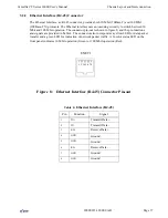
Ethernet Interface (RJ-45) Connector
The Ethernet Interface, an RJ-45 connector, provides both 10 Mbit (10Base-T) and 100 Mbit
(100Base-TX) protocols. The Ethernet interface uses autosensing circuitry to switch between 10
Mbit and 100 Mbit operation. The connector pin-out is shown in figure 8, and the pin functions
and signals are provided in Table 4. The connector also incorporates a yellow LED for data packet
transfer and a green LED for indication of network packet traffic. A bi-color status LED on the
front panel indicates 10 Mbit operation (Green) or 100 Mbit operation (Red).
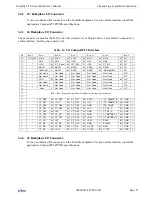
Figure 8: Ethernet Interface (RJ-45) Connector Pin-out
Table 4:
Ethernet Interface (RJ-45)
Pin
Function
Signal
1
TX+
Transmit Data+
2
TX-
Transmit Data-
3
RX+
Receive Data+
4
GND
Ground
5
GND
Ground
6
RX-
Receive Data-
7
GND
Ground
8
GND
Ground
ENET1
1 2 3 4 5 6 7 8


