background image


Manual # 26-0002901-00 / Revision H                                        ScreenPro - High Resolution Seamless Switcher   

60


PROTOCOL INDEPENDENT COMMANDS 


The following commands can be sent to the ScreenPro regardless of the protocol selected. 

External Key Code <TKC KeyCode> 

Description:


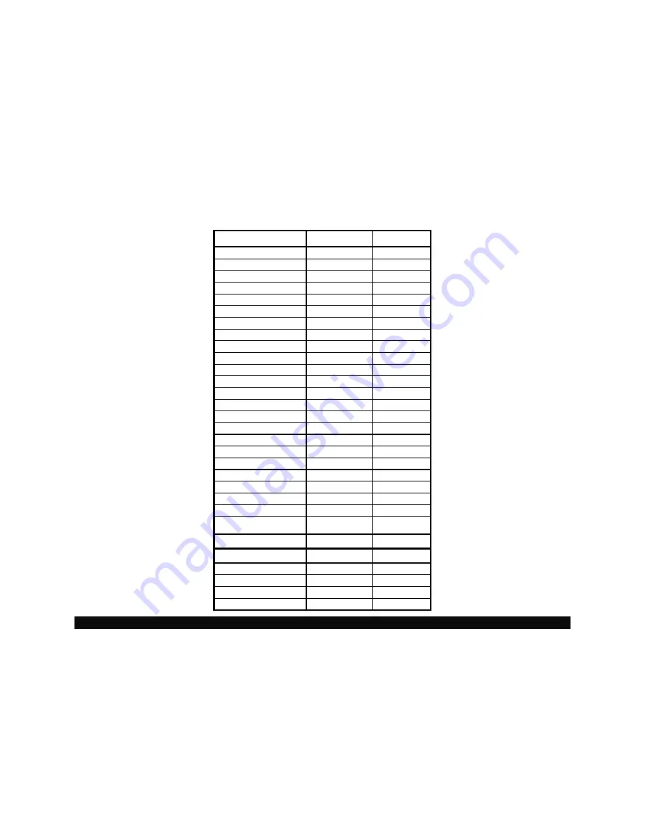
Issued by the Controller to send the “keycode” (see Table 2) for the  

currently pressed key or key combination. 
 

Note: “KeyCode” is a hexadecimal key code expressed in ASCII format. 


Example:


TKC 13 – sends DSLV key depression. 


Table 2: Switch Key Code Assignments 

Note: UP and DOWN Adjust can be used in place of the TER command described below. 


NAME SWITCH 

KEY 

CODE

PROG ADV 

 1 

1F 

MISC 2 

1E 

FILE 3 

1D 

PROG STEP 

1C 

EFFECT 5  1B 
INPUT SETUP 

1A 

OUTPUT SETUP 

19 

PRE MENU 

18 

PROG REV 

17 

DEL 10 

16 

INS 11 

15 

CUT 12 

14 

DSLV 13 

13 

WIPE 14 

12 

FREEZE 15 11 
BLK 16 

10 

8 17 

0F 

7 18 

0E 

6 19 

0D 

5 20 

0C 

4 21 

0B 

3 22 

0A 

2 23 

09 

1 24 

08 

UP ADJUST 

NA 

07 

DOWN ADJUST 

NA 

06 

SELECT 25 3F 
PROG 26 

5F 

CLEAR PROGRAM NA 

56 

FACTORY RESET  NA 

76 

Summary of Contents for ScreenPro SPR-2000

Page 1: ...INSTALLATION AND OPERATOR S MANUAL Model SPR 2000 ScreenPro High Resolution Seamless Switcher Manual 26 0002901 00 Revision H ...

Page 2: ......

Page 3: ...tion section for the Main and Preview Outputs Revised Ch 3 Output Setup Menu Color Balance section Updated the Miscellaneous Menu section by adding System Save feature and revised the SP Ext Control Menu section Updated Ch 5 regarding the Remote Commands that reflect System Save feature and the WIN command feature Updated T O C E Hufana C Yacob F 10 25 02 954 Revised for Letterbox mode addition to...

Page 4: ......

Page 5: ...o alert the user to the presence of important operating and maintenance servicing instructions in the literatureaccompanying the appliance AVERTISSEMENT Le point d exclamation dans un triangle equilatéral signale à alerter l utilisateur qu il y a des instructions d operation et d entretien tres importantes dans la litérature qui accompagne l appareil WARNING VORSICHT ein Ausrufungszeichen innerhal...

Page 6: ......

Page 7: ...ust be capable of that resolution Step 2 Connect Input Sources to ScreenPro TM ScreenPro TM has eight universal inputs that accept composite NTSC PAL S video component and computer video sources Connect each type of input source to ScreenProTM as indicated in the following table Input Connections Format RGB Typical Devices Computers Format YUV or Y Pr Pb Betacam Typical Devices DVD Player or Betac...

Page 8: ...Proper projector setup is critical to optimize the quality of the output image Once ScreenPro s output is set to match the native resolution of the projector the scaling engine in the projector should be disabled The methods used to disable the internal scaler within the projector vary from manufacturer to manufacturer ScreenPro s Output Setup menu allows the user to select test patterns that are ...

Page 9: ...3 Main Preview Source Select Keys 13 Transition Effects 13 Video Mixing and Graphics Overlay Effects Luminance Keying 14 Keying Operation 14 PIP Operation 14 Standard Wipe Transitions 15 Freeze Effect Key 15 Program Keys 15 Program Key PROG 15 Insert Key INS 16 Delete Key DEL 16 Program ADV Key 16 Program REV Key 16 Program Clear 16 Reviewing Program Steps 16 Menu Operation 16 Input Setup Menu Sta...

Page 10: ...8 PIP X POS PIP Y POS 28 File Menu 28 IN1 IN8 28 Delete A File 29 Miscellaneous Menu 29 System Save 29 Config Serial 30 Tech Support Menu 30 Backlight Menu 31 SP Ext Control Menu 31 Ext Remote Control Menu 31 Factory Reset 31 Factory Reset Submenu 32 CHAPTER FOUR 33 Serial Command Syntax Specification 34 Serial Parameters 34 Protocol Mode Selection 34 RS232 Mode 34 Error Codes 34 RS485 Mode 35 Sin...

Page 11: ...izontal Width Inquiry 46 Input Raster Size Position 46 Input Color Balance Saturation 46 Input Sync Selection 46 Keying Command 47 Video Lock Query 47 Letter Box Mode 47 Loader Mode 48 Motion Adaptive De interlace Bypass 48 Marker Placement 48 Output Resolution Select 49 Output Frame Rate Select 49 Output Sync Adjust 49 Output Test Pattern Enable 50 PIP Command 51 Progressive Frame Sequence 3 2 Se...

Page 12: ...play Put Character 62 Display Put String 62 Display Stored String 62 Display Clear Region 62 Display Intensity 62 Display on or off 62 CHAPTER SIX 63 SPR 2000 Software Upgrade Instructions 64 Overview 64 Hardware Requirements 64 Software Requirements 64 Connecting to Folsom Research 64 Downloading Necessary Files 64 Installing the Flash File Loader and ScreenPro Files 64 Starting the Flash File Lo...

Page 13: ...Manual 26 0002901 00 Revision H ScreenPro High Resolution Seamless Switcher 1 1 CHAPTER ONE Introduction What you will find in this chapter About the ScreenProTM Features Technical Description ...

Page 14: ...ct line to support fully integrated multi screen events Attention to the Installation and Operation Sections of this manual is important to ensure trouble free operation Should you have any questions regarding the operation of this unit please consult the factory Features The ScreenProTM provides and offers the following features Eight high resolution inputs accommodate composite NTSC PAL s video ...

Page 15: ... by pixel basis If the luminance value of a pixel is below the threshold then the pixel data from the background scaler is displayed If the luminance value of a pixel exceeds the threshold by 16 counts then the pixel data from the foreground scaler is displayed If the luminance value is between the threshold value and threshold value plus sixteen then a linear mix is performed between the two scal...

Page 16: ......

Page 17: ...igh Resolution Seamless Switcher 5 2 CHAPTER TWO INSTALLATION What you will find in this chapter Rear Panel Connectors Rack Mount Installation Power Cord Line Voltage Selection Video Input Output Connections RS 232 485 Remote Control Connections ...

Page 18: ... 1 2 1 2 3 4 3 4 1 2 3 4 WITH SAME TYPE AND RATING OF FUSE AGAINST RISK OF FIRE REPLACE ONLY CAUTION MAIN 1 V 5 6 B CB H C G Y 5 6 5 6 7 8 V 7 7 O U T P U T S 8 B H C 8 G OUT IN PREVIEW MAIN 2 R E M O T E S E R C R A E 100 240 V Model FOR CONTINUED PROTECTION R CR 5 6 7 8 R C US Display Lock T250V 4A FUSE H Figure 2 1 ScreenProTM Rear Panel Bottom Unit shown with Optional Display Lock feature inst...

Page 19: ...y circuit Reliable grounding earthing of rack mounted equipment should be maintained Power Cord Line Voltage Selection ScreenPro TM is rated to operate with the following supplies Input Power 85 264 VAC 47 63 Hz Power Consumption 175 watts maximum The ScreenPro TM High Resolution Seamless Switcher performs line voltage selection automatically No user controls are required for line voltage selectio...

Page 20: ...erator can select the type of output sync to match application requirements Separate C Composite or separate H V Horizontal Vertical sync modes are supported Connect the outputs labeled R G and B on the rear panel of the ScreenPro TM unit to the correspondingly labeled connectors on the output device Connect the C or H V sync signals from ScreenPro TM to the correspondingly labeled connectors on t...

Page 21: ...f the ScreenProTM unit The Electronics Industry Association EIA has produced standards for RS232 and RS485 that deal with data communications Below is the pinout for both RS232 RS485 with DB25 connector Remote Port DB25 RS232 RS485 1 Shield Shield 2 TxD T 3 RxD R 4 RTS N A 5 CTS N A 6 DSR N A 7 Sig Gnd Sig Gnd 8 DCD N A 10 N A N A 12 N A N A 14 N A T 15 N A N A 16 N A R 19 N A N A 20 DTR N A 21 25...

Page 22: ......

Page 23: ...TER THREE Operation What you will find in this chapter Front Panel Controls Restarting the Program Menu Operation RBG S Video Composite Beta MII and EBU Color Balance and Processing Submenus Output Setup Menu Program Step Menu Input Setup Menu Effects Menu PIP Operation Keying Operation ...

Page 24: ...Switcher 12 Operation Front Panel Controls NOTE Rear Panel features are shown in Chapter 2 Figure 3 1 ScreenPro TM Front Panel 1 Menu Select 2 Preview and Main Source Select 3 Transition Effect Keys 4 Menu Adjust Select Prev Menu 5 Program Setup 6 Program Step 7 Freeze ...

Page 25: ...selection keys will be white The default power up condition is to set BLK black screen input as the Main source and Source 1 as the Preview source The user can easily select any of the input sources as the current Preview source simply by pushing the corresponding Source Select key Each time a new Preview source is selected the key for the selected source will turn green and the video on the Previ...

Page 26: ...ble transition key until the operator changes the wipe type to another function PIP Operation 1 The operator will select the source they want as a picture in picture PIP and this source will be displayed on the preview monitor 2 In the Effects Menu the operator will set the WIPE TYPE to PIP MODE At this point the WIPE key will blink between Red Green and the image in Preview will automatically be ...

Page 27: ...64 transitions and recall the pre programmed transitions using a single key Please note that PIP and Keying effects cannot be used in a program sequence Program Key PROG The PROG key is used to enter Program mode to store program steps When the PROG key is depressed it blinks red and green to indicate that Program mode has been selected In Program mode transitions entered by the operator will be s...

Page 28: ... to move through a pre programmed sequence of steps in reverse order Program Clear To clear all stored program steps simply press the PROG and DEL keys simultaneously Program memory will be cleared as indicated by removal of step display data in the Main Menu Reviewing Program Steps The Program Step menu is used to review the contents of individual program steps Menu Operation The Menu Select keys...

Page 29: ...accepting the changes that have been entered Contrast Brightness The Contrast and Brightness controls allow the operator to adjust the overall contrast and brightness of the image To perform adjustments scroll to the appropriate menu item with the Adjust control select the menu item with the Select key and then turn the Adjust control to perform adjustments while viewing the output screen The adju...

Page 30: ... Type field of the Input Setup menu 2 RGB Color Balance This menu allows the operator to balance the colors on an RGB input source Independent Contrast and Brightness adjustments are provided for each color channel Parameters entered by the operator are saved as part of the input configuration file for the corresponding video input channel To perform adjustments scroll to the desired menu line sel...

Page 31: ...r to adjust saturation on Beta 50 Beta 60 MII and EBU input sources Parameters entered by the operator are saved as part of the input configuration file for the corresponding video input channel To perform adjustments scroll to the Saturation menu line select the menu item with the Select key and then turn the Adjust control to select the desired saturation level while viewing the output screen Pr...

Page 32: ... mode is DC Restoration to the back porch of the incoming video signal PRCH The PDLY Mode is used when a tri level sync comes in on the input such as an HDTV signal The SYNC Mode selects DE Restoration to the sync interval and may be useful for videos without a back porch interval 4 De Interlacer This menu item is applicable only for NTSC or PAL input video The De Interlacer should be on for optim...

Page 33: ... reflect parameters entered by the operator Note that if no file has been entered default file number and name data will be assigned Save As The Save As menu item saves the input setup parameters as a configuration file which is then automatically assigned to the source used for the input setup process The configuration file is automatically recalled each time the source is selected Note The funct...

Page 34: ...ces a superior image by sampling the analog graphics signals at exactly the same rate as that of the original source This allows the image to be re construction with the reduced digitizing artifacts This 1 1 Sampling approach requires very accurate settings and even a small sampling error causes noise on the output image Both the sample clock frequency and phase must be correct to obtain a properl...

Page 35: ...o the Phase Main menu item pressing Select and making adjustments with the Adjust Control This menu field displays a number between 16 and 15 which represents phase adjustment for the sample clock on the Preview output Phase is adjustable to the nearest 1 32 of a clock period This parameter is automatically loaded when the Auto Config process is complete Manual adjustments can be made by scrolling...

Page 36: ...tifacts it is recommended that the output frame rate be set to match the input frame rate for video sources 59 94 Hz for NTSC 50 Hz or 75Hz for PAL When the frame rate is set to 75Hz the following resolutions cannot be selected SXGA SXGA 2 1280x960 and 1365x1024 Sync The Sync menu items allow the user to independently select the desired output sync format for the Preview and two Main outputs To pe...

Page 37: ...eenPro units to have their outputs synchronously locked together This is achieved by having one ScreenPro act as a master timing unit The other ScreenPros are slaved to the master unit and lock their output timing to the master unit See the diagram below for help in connecting units together ScreenPro Master Display Lock IN ScreenPro Slave Display Lock OUT ScreenPro Slave Display Lock OFF Display ...

Page 38: ...programmed sequences of transitions This permits an entire show to be scripted and controlled via the Program Advance and Program Reverse keys on the front panel The operator can view each program step using the Program Step menu by activating PROG STEP Menu Select Key Step Number The Step Number menu item allows the user to select the number of the program step to be viewed To select a specific p...

Page 39: ...HOLD menu item with the Select key and then turn the Adjust control to select the desired threshold between 0 and 100 To get an idea of how the threshold affects the final mix transition the key source over the background image before adjusting the threshold Edge Adj To control the edge width of the transition select the EDGE ADJ menu item with the Select key and then turn the Adjust control to se...

Page 40: ... Size 710 2 1024 100 34 67 Min Vertical Size 485 2 768 100 31 58 PIP sizes smaller than the calculated limits can still be used However the right and bottom edges of the screen will be cropped PIP X POS PIP Y POS To control the Horizontal or Vertical Position of the PIP select PIP X POS or PIP Y POS menu item and then turn the Adjust control to position desired between 0 and 100 File Menu The File...

Page 41: ... Miscellaneous Menu The Miscellaneous Menu has options for changing added user configurations System Save The System Save allows the user to save system parameters which are restored upon power up These parameters include the intensity of the display menu configuration of the effects menu effect type duration PIP parameters and the initial state of video source select inputs On power up these para...

Page 42: ...rts NONE EVEN or ODD RESET will default the settings to Baud 38 4 Parity None Data Bits 8 and Parity None RS 485 Menu RS 232 Menu Tech Support Menu Displays the latest version of software and customer service numbers to contact in case of emergency RS 485 PORT MENU ID 1 BAUD RATE 38 4K DATA BIT 8 STOP BIT 1 PARITY NONE RESET RS 485 RS 232 PORT MENU ECHO ON BAUD RATE 38 4K DATA BIT 8 STOP BIT 1 PAR...

Page 43: ...s with an external controller User has the option between STANDALONE SPR EXT ID 1 SPR EXT ID 2 SPR EXT ID 3 SPR EXT ID 4 SPR EXT ID 5 SPR EXT ID 6 SPR EXT ID 7 or SPR EXT ID 8 The BKGND MODE field is reserved for future use and cannot be changed Factory Reset To reset ScreenPro TM to factory default settings depress and hold down the PROG key and DEL key and press the Select key The front panel wi...

Page 44: ...enPro High Resolution Seamless Switcher 32 Factory Reset Submenu Pressing the Select key will perform a factory reset Pressing Prev Menu key will return the user to the previous menu DELETE ALL USER FILES AND RESET SELECT YES PREV MENU NO ...

Page 45: ...6 0002901 00 Revision H ScreenPro High Resolution Seamless Switcher 33 4 CHAPTER FOUR Serial Command Syntax Spec s What you will find in this chapter Serial Parameters RS 232 RS 485 Mode Download CFG Upload CFG ...

Page 46: ...mmand typically 2 to 6 alphabetic non numeric characters arg arg1 arg2 argn are required or optional parameters depending on the command used CR carriage return ASCII 13 terminates the command A space ASCII 32 must be inserted between the command and any arguments that follow A space must also be inserted between all argument parameters except for the last argument in the chain All commands in RS2...

Page 47: ...il the cde character is received This format allows commands to be stack to the same or multiple devices and executed when the cde character is received by all units Any incomplete or unknown commands will be ignored The maximum number of commands that can be stacked per unit is 16 Each unit will only stack those commands assigned to it even though all units receive the same command string During ...

Page 48: ...or Program Sequence Steps nn Selects the index number of the configuration When Op I the number can be between 1 64 for a User Library Configuration Use 0 to load the file into the index it originated from When Op P the number needs to be 1 S 8 Optional parameter to override the 8 character description of the file Example UL I 3 CR Uploads file to the input cfg location 3 This command will upload ...

Page 49: ...he following values 1 Dissolve Note A Cut is a dissolve of 0 0 seconds 2 Wipe Right 3 Wipe Left 4 Wipe Down 5 Wipe Up 6 Curtain Open 7 Curtain Close 8 Mosaic Example 12410 029551 2 defines a two sequence program file with a cut to source 2 at step 1 and a wipe up transition of 1 2 seconds to source 9 BLK key with an edge with of 8 pixels at step 2 ...

Page 50: ...0002901 00 Revision H ScreenPro High Resolution Seamless Switcher 38 5 CHAPTER FIVE Remote Commands What you will find in this chapter Remote Commands ScreenProTM Command List Description Terminal Remote Control ...

Page 51: ...S485 ID Number n 1 32 IHRE sclr Input Right Edge Inquiry sclr A B M P IHUE nnn sclr Input Hue n 0 360 degrees sclr A B M P IHW sclr Input Horizontal Width Inquiry sclr A B M P IRSP op nnn sclr Input Raster Size Position op L R T B n 999 999 ISAT nnn sclr Input Saturation n 50 200 sclr A B M P ISYNC n sclr Input Sync n 0 3 SOG COMP H V AUTO sclr A B M P KEY mode sclr thrsh Luminance Keying mode K X...

Page 52: ... n n n n Window Zoom n 0 1 Disable Enable sclr A B n 0 100 n 0 100 n 0 100 n 0 100 ScreenProTM Command List Description Allow Input Size Adjust AOIWN Description Allows sizing adjustments of the input source with respect to the output raster Parameters n Right Edge n Horizontal Width Pixels n Bottom Edge n Vertical Height Lines sclr Scaler A B M P Scaler A Scaler B Main Preview Example AOIWN A Ret...

Page 53: ...steps Echo Command ECHO Description Enable or Disable ECHO Parameters port Com Port A B Note Com A 25 pin Remote Port n Disable or Enable 0 1 Example ECHO A 0 Disable ECHO on Com A Freeze Command FREEZ n sclr Description Enable Disable Freeze Parameters n Freeze Enable Disable n 0 1 OFF ON sclr Scaler A B M P Scaler A Scaler B Main Preview Example FREEZ 1 A Enables freeze on the display on Scaler ...

Page 54: ...the Input Brightness on Scaler A to be 110 5 IBRT R 10 M Adjusts the Red Offset to 10 for the Input on Main Input Configuration Delete ICDEL nn Description Deletes a specified Input Configuration Parameters nn Input Configuration Index n 1 64 Example ICDEL 2 Deletes input configuration two Input Configuration File Name Query ICFGN n Description Fetch input configuration file name Parameters n File...

Page 55: ...ample ICPH A P Automatically adjust the Input Clock Phase on Preview ICPH M M 12 0 Set Input Clock Phase on Main to 12 for the currently displayed input ICPH M M 12 2 Set Input Clock Phase for File Number 2 to 12 ICPH I A 3 Increment the Input Clock Phase on Scaler A by 3 Input Clock Phase Offset Adjust ICPHO op sclr nn Description Adjust the Input Clock Phase Offset Parameters op A D M I Automati...

Page 56: ... by 4 Input Configuration Recall ICREC nn sclr n Description Recalls a stored Input Configuration Parameters nn Input Configuration Index n 1 64 sclr Scaler A B M P Scaler A Scaler B Main Preview n Router input to which the input signal is connected Note Router Input parameter only used on ScreenPro Plus Example Assuming there is a saved Input Configuration in Index 1 ICREC 1 M Loads the Input Con...

Page 57: ... or 255 then selection will increment or decrement through the list sclr Scaler A B M P Scaler A Scaler B Main Preview Example ICSP 0 A Adjusts the Input Color Space on Scaler A to be RGB System ID ID n Description Set system ID for use under RS 485 protocol Parameters n ID Number 1 32 Example ID 3 Sets the unit ID to 3 Input Right Edge Inquiry IHRE sclr Description Input Right Edge Inquiry Parame...

Page 58: ...lue 999 999 sclr Scaler A B M P Scaler A Scaler B Main Preview Example IRSP R 10 A Increments the Right Input Raster Size Position by 10 on Scaler A Input Color Balance Saturation ISAT nnn sclr Description Adjusts the Input Color Balance Saturation Only applicable if input is a NON RGB source Parameters nnn Input Saturation n 50 200 sclr Scaler A B M P Scaler A Scaler B Main Preview Example ISAT 1...

Page 59: ...reshold Query of Key Command KEY SCLR SCLR A B P or M P M stand for preview and main Returns a nnn1 Where a K Key Mode On X Key Mode Off W is window mode for use with PIP or Z is both Key and Windowing are ON nnn1 THRESHOLD Range 0 to 100 Video Lock Query LCK sclr Description Video Lock Inquiry Command Parameters sclr Scaler A B M P Scaler A Scaler B Main Preview Returns 0 for NOT LOCKED 1 for LOC...

Page 60: ... Example MADB 0 A Disable the Motion Adaptive De Interlacing Marker Placement MARKER n hpos Description Command will overlay a green vertical line 2 pixels wide at the horizontal position indicated The line will appear on either Preview or Program monitor based on the current Raster Box setting of PREVIEW MAIN or BOTH If the Raster Box is OFF then the line will default to the Preview monitor Param...

Page 61: ... 0 10 Note When the frame rate is 75Hz the following resolutions cannot be selected SXGA 1365x1024 1280x1024 II and 1280x960 When the frame rate is 60Hz only 1280x768 can be selected Output Frame Rate Select Command OFRATE n saveFlag Description Select the Output Frame Rate to use Parameters n Output Frame Rate n 0 3 59 94Hz 50Hz 75Hz 60Hz saveFlag OPTIONAL PARAMETER 0 Do NOT Save selected output ...

Page 62: ...on Use to select Test Pattern options Parameters m Overlay Mode m 0 3 OFF ON Main Only ON Preview Only ON Both Scalers This is the overlay mode for the Raster Box and Grid The parameter is only applicable when TPMODE is DISABLED When TPMODE is ENABLED the test pattern selected will be shown on both Main and Preview However when TPMODE is enabled you must still place a number in this location when ...

Page 63: ...f or W is window mode for use with PIP nnn1 HWIDTH Range 0 to 100 nnn2 VWIDTH Range 0 to 100 nnn3 HSTART Range 0 to 100 nnn4 VSTART Range 0 to 100 Progressive Frame Sequence 3 2 Select Command PFSD n sclr Description Progressive Frame Sequence Detection This command will allow the detection of 3 2 pulldown to be enabled or disabled Parameters n n 0 1 Disable or Enable sclr Scaler A B M P Scaler A ...

Page 64: ...re 0 RS 232 and 1 RS 485 Example SMODE 1 Sets the ScreenPro for RS 485 Communication Command SSTAT Description FACTORY USE ONLY Example SSTAT A Returns a system status value STAT Description FACTORY USE ONLY Parameters None Example STAT Returns a system status value Save System Parameters Command SSAVE Description This command will save all the ScreenPro s parameters to non volatile memory Paramet...

Page 65: ...display Terminal Backlighting Select Command TBLS n Description Enable or Disable the backlighting on the front panel switches Parameters n 0 1 Disable Enable Example TBLS 0 This will turn off the backlights on the front panel switches Terminal Remote Control Mode Command TCM n Description This command sets the Remote Control mode for the ScreenPro Refer to the Terminal Remote Control section of t...

Page 66: ...kwise motion by a small amount Terminal Front Panel Switch Select Command TKC nn Description Allows a remote control unit to emulate the function of any switch on the front panel Parameters nn 06 7F Each switch has a unique hex code association This number needs to be transmitted in ASCII format See the table below SWITCH NAME CODE PROG ADV 1F MISC 1E FILE 1D PROG STEP 1C EFFECT 1B INPUT SETUP 1A ...

Page 67: ...er nn 1 64 Example TRCF 4 2 Sets up Input source 4 to use File 2 Transition Preview to Main Command Command TRN dst dn n n n Description Use to transition Preview onto the Main output display Parameters dst Final Input dst A B M P n Transition Edge Width dn Transition Numbers 0 256 pixels 1 Dissolve 1 128 pixels 2 Wipe Right 2 64 pixels 3 Wipe Left 3 32 pixels 4 Wipe Up 4 16 pixels 5 Wipe Down 5 8...

Page 68: ... 1 FULL REDUCED sclr Scaler A B M P Scaler A Scaler B Main Preview Example VBW 0 P Set the video bandwidth on Preview to Full Version Query Command VER Description This is a version query The return format is nn nn a where nn is a two digit software version nn is a two digit software version a is an alpha character Parameters None Example VER Will return nn nn a to a terminal emulator Video Peakin...

Page 69: ...ontal width or vertical width is greater than 100 Parameters pipen 1 0 enable or disables PIP sclr A B scaler to apply this command hcenter 200 200 horizontal center of PIP hwidth 0 400 horizontal width vcenter 200 200 vertical center vwidth 0 400 vertical width Example Example 1 WIN 1 A 0 50 0 50 cr PIP enabled apply to scaler A 0 is center of PIP image horizonatal image at 50 of normal 0 is cent...

Page 70: ... This protocol is an extension of the Folsom protocol It allows controllers to receive the background commands that are sent to the Front Panel in order to keep its LED s and Display updated whenever switches are pressed or the knob is turned This protocol is NOT compatible with RS485 PROTOCOL SELECTION Remote Control Mode TCM type Description Issued by the Controller to set the Graphics board con...

Page 71: ...that the RUN ADV LED is red the MISC LED is green the FILE LED is blinking and all other LEDs are off The strings ooyooooooooooooooooooooooo and oorooooooooooooooooooooooo are transmitted to indicate that the FILE LED is blinking alternatively yellow and red See Table 1 for the switch number assignments If the FSR protocol mode is selected then the following will be true The response for the TLSR ...

Page 72: ...l key code expressed in ASCII format Example TKC 13 sends DSLV key depression Table 2 Switch Key Code Assignments Note UP and DOWN Adjust can be used in place of the TER command described below NAME SWITCH KEY CODE PROG ADV 1 1F MISC 2 1E FILE 3 1D PROG STEP 4 1C EFFECT 5 1B INPUT SETUP 6 1A OUTPUT SETUP 7 19 PRE MENU 8 18 PROG REV 9 17 DEL 10 16 INS 11 15 CUT 12 14 DSLV 13 13 WIPE 14 12 FREEZE 15...

Page 73: ...in order to change the Front Panel status LED Blink TLB led state1 state2 On Off Description Blinks the LED selected by the parameter led between the two states indicated state1 and state2 if the on off parameter is set to on one Blinking is disabled when the on off parameter is set to zero Note if led is set to zero all of the LEDs will be activated Note state is defined as o y r g off yellow red...

Page 74: ...ations and displays it starting at row and column Example TDSS 243 2 0 Places the string stored at offset 243 on line 3 of the display starting at t he far left Note For further information regarding this command and obtaining a copy of the text file with string definitions and offset locations contact Folsom Research Inc Display Clear Region TDCR row1 col1 row2 col2 Description Clears the display...

Page 75: ...l 26 0002901 00 Revision H ScreenPro High Resolution Seamless Switcher 63 6 CHAPTER SIX SPR 2000 Software Upgrade Instructions What you will find in this chapter Overview Preparing to Upgrade ScreenPro Unit ...

Page 76: ...sing a FTP client logon to our site using anonymous for the user name and your email address as the password ex johndoe somecompany com If you are using a web browser to access our FTP site point the browser to ftp ftp folsom com Downloading Necessary Files SPR 2000 Software Files and Flash File Loader Directory Location ftp folsom com products video spr2000 File to download ScreenPro_Rev exe wher...

Page 77: ... DCD status lights are GREEN then check the communication settings in the loader and verify the COM port is correct and the communication parameters match with what is displayed in the CONFIG SERIAL menu on the Screen Pro unit 6 If any of the communication parameters are changed within the loader it is recommended that the Screen Pro unit be powered down and the verification process started over U...

Page 78: ...2901 00 Revision H ScreenPro High Resolution Seamless Switcher 66 7 CHAPTER SEVEN Folsom Research Information What you will find in this chapter Warranty RMA Information Technical Support General Contact Information ...

Page 79: ...eceive a Return Merchandise Authorization number RMA RMA Conditions a Prior to returning any item you must receive a Return Merchandise Authorization RMA number b All RMA numbers must appear on their return shipping label c RMA numbers are valid for ten 10 days from issue date d All shipping and insurance charges on all RMA s must be prepaid by the customer Folsom Research Contact Information Sale...

Page 80: ......

Page 81: ...Manual 26 0002901 00 Revision H ScreenPro High Resolution Seamless Switcher 69 8 APPENDIX Technical Specifications ...

Page 82: ...onnectors Main Outputs Two independently buffered outputs 1 RGBHV with an HD 15 1 RGBHV with five BNC connectors Preview Output 1 RGBHV with an HD 15 Format User selectable in the following formats VGA 640x480 SVGA 800x600 XGA 1024x768 SXGA 1280x1024 Plasma formats including 1280x720 1280x768 1365x768 1365x1024 Syncs User selectable H V or C with selectable polarities Frame Rate User selectable 50...

Page 83: ...and 8 keys provide a menu based front panel interface to support all setup functions Remote Control Reconfigurable RS 232 485 DB 25 port for real time control Physical Height 5 25 13 3 cm Width 17 43 2 cm or 19 48 3 cm with rack mount option Depth 13 33 cm Weight 22 lbs 10 kg Shipping Weight 30 lbs 13 6 kg Input Power 85 264 VAC 47 63 Hz 175 W max Environmental Temperature 0 40 degrees C Humidity ...

Reviews: