10
- ORIGINAL INSTRUCTIONS -
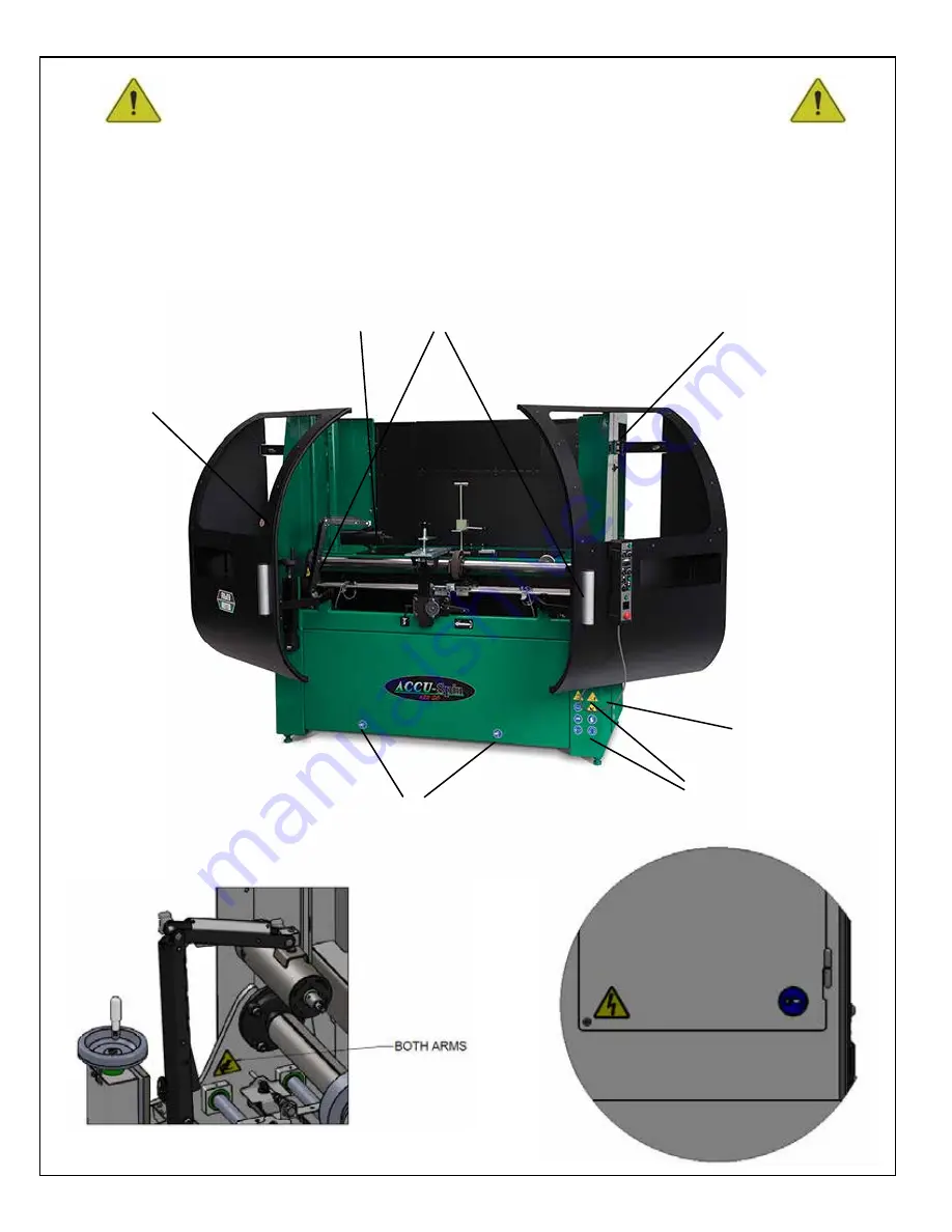
SAFETY INSTRUCTIONS
SAFETY DECALS - LOCATION.
IF ANY DECALS ARE DAMAGED, REPLACE THEM IMMEDIATELY!
See next page for explanation of symbols and decals.
1-7
8, 13
9
11, 17
12
14
15, 16
Page 1: ...e OPERATOR S MANUAL which contains all the information to install operate and perform daily maintenance on this equipment The SERVICE MANUAL which is used by the maintenance department to do all maint...
Page 2: ...ring the highest quality products at an unequaled value Setting the industry standard by investing in technological product innovation Manufacturing products specifically designed to maintain original...
Page 3: ...o 5 321 912 6 010 394 6 290 581 6 685 544 6 699 103 additional Patents Pending OPERATOR S MANUAL 6227950 11 21 You must thoroughly read and understand all manuals before operating the equipment paying...
Page 4: ...nd safety signs is not qualified to operate the unit Accidents occur often on machines that are used by someone who has not read the operators manual and is not familiar with the equipment If you do n...
Page 5: ...d vs quality 11 Understand General Maintenance Before using this equipment refer to the list below Verify that all of the listed items are completed before powering up the equipment Keep this manual h...
Page 6: ...TY 50 Relative Humidity 40 C 100 F Higher Relative Humidity may be allowed at lower temperatures There must not be condensation present ALTITUDE Up to 1000m 3280 ft above mean sea level TRANSPORTATION...
Page 7: ...t Look for signs of wear loose hardware and missing or damaged components Ensure connections are tight and hoses and tubes are in good condition 2 Clean the machine by wiping it off 3 Remove all grind...
Page 8: ...EGIBLE If safety decals become damaged or illegible for any reason replace immediately Refer to replacement parts illustrations in Service Manual for the proper location and part numbers of safety dec...
Page 9: ...CEED THE MAXIMUM OPERATING SPEED established for the wheel 4 DON T use mounting flanges if the bearing surfaces ARE NOT CLEAN FLAT AND FREE OF BURRS 5 DON T TIGHTEN the mounting nut excessively 6 DON...
Page 10: ...10 ORIGINAL INSTRUCTIONS SAFETY INSTRUCTIONS SAFETY DECALS LOCATION IF ANY DECALS ARE DAMAGED REPLACE THEM IMMEDIATELY See next page for explanation of symbols and decals 1 7 8 13 9 11 17 12 14 15 16...
Page 11: ...be a trip hazard Secure the power cord in a manner that removes it as a trip hazard Unplug the machine when servicing or storing for an extended period of time POWER CORD PROTECTION The power supply c...
Page 12: ...nit across two concrete slab seams or across a large crack PLACING THE GRINDER ON FLOORING THAT IS NOT LEVEL OR BROKEN WILL AFFECT GRINDING QUALITY MACHINE MUST BE POSITIONED TO ALLOW EASY ACCESS TO T...
Page 13: ...heck with level after locking nuts are firmly tightened FIG 4 FIG 6 FIG 5 LOOSEN JAM NUT TO ADJUST FOOT LEVELING FEET LOCATED AT CORNERS OF MACHINE THE EQUIPMENT SHOULD NEVER BE LEFT UNATTENDED WHEN R...
Page 14: ...ONNECTOR THAT COMPLIES TO THE LOCAL LAWS AND REGULATIONS SHOULD BE INSTALLED BY A QUALIFIED ELECTRICIAN THE PLUG IS CLASSIFIED AS A CATEGORY 0 MAIN DISCONNECT DO NOT WIRE THIS MACHINE DIRECTLY TO A PO...
Page 15: ...nstalled if there is not one already on the end of the main power cord USE ONLY A QUALIFIED ELECTRICIAN TO COMPLETE THE INSTALLATION FIG 8 1 Individually wire nut Transformer Leads H2 H3 H4 H7 H8 and...
Page 16: ...nit 3 CONTROL Contains the switches and knobs for the operator to use through the Spin and Relief grind processes 4 REAR ROLLER SUPPORTS Allows for easy adjustment of the rear roller using the V Mount...
Page 17: ...control and related components Disconnect the cord at the wall outlet before performing service FUSES Interrupts excessive current blows so that further damage by overheating or fire is prevented THI...
Page 18: ...oin is not used to use in the future STEP 1 PLACING THE CUTTING UNIT PREPARE CUTTING UNIT FOR SHARPENING 1 Follow the cutting unit manufacturers recommendations for proper maintenance when preparing t...
Page 19: ...preader bar onto the reel The clamps on the spreader bar should be spaced evenly along the mower so the clamps do not slide as the mower is being raised OPTIONAL ELECTRIC WINCH Use the WINCH CONTROL c...
Page 20: ...winch cool down 12 DO NOT OPERATE WORKSTATION WINCH WHEN UNDER THE INFLUENCE OF DRUGS ALCOHOL OR MEDICATION 13 DO NOT USE WORKSTATION WINCH TO HOLD LOADS IN PLACE Use other means of securing loads su...
Page 21: ...nized aircraft type 1 8 DIA 3 mm 7 x 19 cable Always replace the wire rope with the replacement rope specified in the parts section of this manual Because all rope is subject to wear it is excluded fr...
Page 22: ...ing unit true the REAR ROLLER SUPPORT PLATE to parallel to the V BLOCKS SUPPORT to the Grind shaft To move Unlock the LOCK HANDLES on the rear tooling plate and rotate the HANDWHEEL until the POINTER...
Page 23: ...cutting unit into the V BLOCKS as shown above It may be necessary to move the FRONT HEIGHT ADJUSTER into a position to receive the front roller This is done by unlocking the LOCK HANDLE and sliding t...
Page 24: ...that came with the checking device To maintain the best quality of cut the taper in a reel must be removed returning the reel to a true cylinder To remove the taper that was measured with the checker...
Page 25: ...BUTTON and hold for three seconds to reset the ACCU POSITIONING GAUGE to reset the guage All three LEDs will blink twice to indicate that the GAUGE is reset fig 19 fig 18 LED INDICATORS Indicates Tur...
Page 26: ...nter shaft of the cutting unit NOTE It is important to NOT move the gauge forward or back if this occurs your readings will be skewed 7 Press the RESET CHECK BUTTON to take the second reading The BLUE...
Page 27: ...ligns with the decal on the tooling bar see FIG 19 8 Release the tab and allow the GAUGE PIN to travel up to the the center shaft of the cutting unit NOTE It is important to NOT move the gauge forward...
Page 28: ...DRIVE MOTOR with the correct adapter This will generally be the same drive system component used for backlapping see FIG 28 The SPIN DRIVE MOTOR attaches to the end of the reel shaft or a drive syste...
Page 29: ...L until the wheel has cleared the end of the reel if clearance to the frame allows see FIG 29 4 When the GRINDING WHEEL is in position move the TRAVEL LIMIT SENSORS in until the light on the SENSOR il...
Page 30: ...l down until you can travel the full length of the reel without heavy grinding When you are able to travel the full distance of the reel without any problems proceed with grinding the reel 7 To manual...
Page 31: ...s with the grinding wheel and the resonance vibrates the grinder which results in a very bad grind By changing the SPIN SPEED to a higher or lower RPM you will move out of the resonant range After det...
Page 32: ...32 ORIGINAL INSTRUCTIONS...