background image

3-5

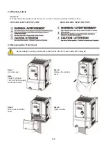
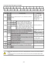
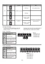
3.4 Warning Labels 

Important: 

Warning information located on the front cover must be read upon installation of the AC Drive. 
 

240V 0.5HP–20HP / 480V 1HP–25HP

      240V 25HP–40HP / 480V 30HP–75HP 

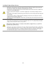
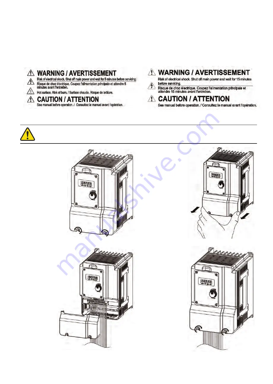
3.5 Removing the Front Cover

Before making any wiring connections to the AC Drive the front cover needs to be removed.

Step 1:


Unscrew cover 

 
Note:


0.5HP–1HP 240V, 
1HP–2HP 480V models 
do not use screws.

Step 2:


Remove the terminal 
cover

Step 3:


Wire and re-install the 
cover

Step 4: 

Tighten screws

Summary of Contents for TD 400 Series

Page 1: ......

Page 2: ......

Page 3: ...8 3 8 Control Circuit Terminals and Jumpers 3 9 3 9 Power Terminals 3 10 3 10 AC Drive Wiring 3 11 3 11 Input Power and Motor Cable Length 3 12 3 12 Cable Length vs Carrier Frequency 3 12 3 13 Installing an AC Line Reactor 3 12 3 14 Power Input Wire Size and NFB 3 13 3 15 Control Circuit Wiring 3 13 3 16 AC Drive derating based on Carrier Frequency 3 13 3 17 Braking resistors 3 14 Chapter 4 User I...

Page 4: ...ation Functions 5 3 5 2 1 Counter Function 5 3 5 2 2 Timer Function 5 5 5 2 3 Analog Comparator Function 5 8 5 2 4 Operation Control Function 5 9 5 2 5 Math Functions 5 10 Chapter 6 Communications 6 1 Modbus Protocol 6 2 6 1 1 Network Connection 6 2 6 1 2 Date Format Frame for ASCII Mode 6 3 6 1 3 Data Frame for RTU Mode 6 3 6 1 4 CRC 6 4 6 1 5 Register and Data Format 6 5 6 1 6 Monitor Data Read ...

Page 5: ...Ω Please check and test emergency stop circuits after wiring Installer is responsible for the correct wiring Never touch any of the input or output power lines directly or allow any input or output power lines to come in contact with the AC Drive case Do not perform a dielectric voltage withstand test megger on the AC Drive This will result in AC Drive damage to the semiconductor components Check ...

Page 6: ...ect or disconnect the motor during operation This will cause the AC Drive to trip and may cause damage to the AC Drive Operations may start suddenly if an alarm or fault is reset with a run command active Confirm that no run command is active upon resetting the alarm or fault otherwise accidents may occur It provides an independent external hardware emergency switch which emergently shuts down the...

Page 7: ...all metal objects such as watches and rings secure loose clothing and wear eye protection before beginning work on the AC Drive Observe proper electrostatic discharge ESD procedures when handling the AC Drive and circuit boards Failure to comply may result in ESD damage to the AC Drive circuitry Do not modify the AC Drive circuitry Failure to comply could result in damage to the AC Drive and will ...

Page 8: ...minals not located within the motor circuit shall be marked to indicate the proper connections that are to be made to each terminal and indicate that copper conductors rated 75 C are to be used AC Drive Short Circuit Rating This AC Drive has undergone the UL short circuit test which certifies that during a short circuit in the power supply the current flow will not rise above value Please see elec...

Page 9: ... the input power requirements 5 Ensure that the motor HP matches the motor rating of the AC Drive 1HP 0 746 kW Product Name and Motor Ra琀ng Input Power Specifica琀ons Output Power Specifica琀ons Series No UL and CE Marks PRODUCT E510 2P5 H U MOTOR RATING 0 5 HP INPUT AC 1 3PH 200 240V 10 15 50 60hz 8 5 4 5A OUTPUT AC 3PH 0 599 Hz 3 1A IP20 NEMA 1 ENCLOSURE IP20 P N BARCODE S N BARCODE TD400 20P5 13PH ...

Page 10: ...8 3 5 480 Frame 3 7 5 10 240 4 AWG 25mm 24 5 21 2 2 4 7 5 15 480 Frame 4 15 20 240 4 AWG 25mm 24 5 21 2 2 4 20 25 480 Frame 5 25 240 2 AWG 35mm 25 5 22 1 2 5 30 480 Frame 6 30 40 240 3 0 AWG 95mm 81 6 70 8 8 40 75 480 Notes Wire size shown is based on maximum terminal size Please consult the NEC or local codes for proper size to be used The wire size assumes a maximum voltage drop of 2 If this val...

Page 11: ... power loss time s 2 2 2 2 Enclosure IP20 NEMA1 Braking Transistor Built in 2 3 AC Drive Specifications 240V Class Single Three phase Model TD400 2005 3PH TD400 27P5 3PH TD400 2010 3PH TD400 2015 3PH Horse power HP 5 7 5 10 15 Motor capacity KW 4 5 5 7 5 11 Rated output current A 17 5 26 35 48 Rated capacity KVA 6 7 9 9 13 3 20 6 Input voltage range V Three phase 200 240V 50 60HZ Allowable voltage...

Page 12: ...3 8 5 3 9 2 Rated capacity KVA 1 7 2 9 4 6 7 Input voltage range V Three phase 380 480V 50 60HZ Allowable voltage fluctuation 15 10 Output voltage range V Three phase 0 480V Input current A 4 2 5 6 7 3 11 6 Circuit Breaker Current Rating 15A 15A 15A 15A Fuse Rating 15A 600VAC 15A 600VAC 15A 600VAC 15A 600VAC AC Drive net weight lbs kg 3 9 1 8 3 9 1 8 5 7 2 6 5 7 2 6 Allowable momentary power loss ...

Page 13: ...ntary power loss time s 2 2 Enclosure IP20 NEMA1 Braking Transistor Built in Optional External Model TD400 4050 3PH TD400 4060 3PH TD400 4075 3PH Horse power HP 50 60 75 HD ND Suitable motor capacity kW 37 45 45 55 55 75 HD ND Rated output current A 75 88 91 103 118 145 HD ND Rated capacity KVA 57 2 67 1 69 3 78 5 89 9 111 Input voltage range V Three phase 380 480V 50 60HZ Allowable voltage fluctu...

Page 14: ...Main Alt Frequency Command PID control torque boost V F start Frequency Fault reset Display LED Display parameter parameter value frequency line speed DC voltage output voltage output current PID feedback input and output terminal status Heat sink temperature Program Version Fault Log LED Status Indicator Run Stop Forward Reverse and etc Protective Functions Overload Protection OL1 Electrical over...

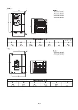
Page 15: ... condensation Compliance with IEC 60068 2 78 Vibration 1G 9 8m s for 20Hz 0 6G 5 88m s 20Hz 50Hz Follow IEC60068 2 6 standard Enclosure IP20 NEMA1 2 5 AC Drive Dimensions Frame 1 Q Q W1 H1 H W D Models TD400 20P5 13PH TD400 2001 13PH TD400 4001 3PH TD400 4002 3PH Dimensions in mm inch W W1 H H1 D Q NEMA 1 Kit H 90 6 3 57 90 6 3 57 164 6 46 153 6 02 151 4 5 96 M4 186 2 7 33 ...

Page 16: ...in mm inch W W1 H H1 D Q NEMA 1 Kit H 128 7 5 07 118 4 65 187 6 7 39 177 6 6 99 152 4 6 M4 213 6 8 41 Frame 3 Models TD400 27P5 3PH TD400 2010 3PH TD400 47P5 3PH TD400 4010 3PH TD400 4015 3PH Dimensions in mm inch W W1 H H1 D Q NEMA 1 Kit H 186 9 7 36 175 6 89 260 9 10 27 249 8 9 83 202 6 7 98 M4 293 5 11 56 W1 H1 W Q D Q H ...

Page 17: ...Dimensions in mm inch W W1 H H1 D Q NEMA 1 Kit H 224 6 8 84 207 8 15 321 6 12 66 303 5 11 95 206 1 8 11 M4 363 3 14 3 W1 H1 W Q D Q H Frame 5 Models TD400 2025 3PH TD400 4030 3PH Dimensions in mm inch W W1 H H1 D Q 265 10 43 245 9 65 360 14 17 340 13 39 238 2 9 38 M8 Q H1 W H W1 D ...

Page 18: ...ame 6 Models TD400 2030 3PH TD400 2040 3PH TD400 4040 3PH TD400 4050 3PH TD400 4060 3PH TD400 4075 3PH Dimensions in mm inch W W1 H H1 D Q 286 5 11 28 220 8 66 525 20 67 505 19 88 269 8 10 62 M8 D Q H1 W H W1 ...

Page 19: ...ambient temperatures below 40 C 104 F Storage Temperature 20 C 60 C 4 140 F Humidity 95 non condensing Relative humidity 5 to 95 free of moisture Follow IEC60068 2 78 standard Altitude 1000m 3 281 ft Installation Site Avoid exposure to rain or moisture Avoid direct sunlight Avoid oil mist and salinity Avoid corrosive liquid and gas Avoid dust lint fibers and small metal filings Keep away from radi...

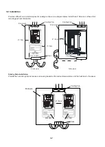
Page 20: ...surfaces that provide good heat dissipation Front view Side view 4 8 12cm 2 5cm 4 8 12cm 2 5cm Enclosure Enclosure Cooling Fan Cooling Fan 2 5cm Vent Vent Side by Side Installation Provide the necessary physical space and cooling based on the ambient temperature and the heat loss in the panel 2 5cm Enclosure Vent Cooling Fan ...

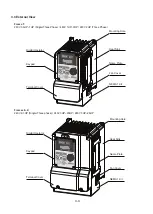
Page 21: ...240V 2HP Three Phase Digital Operator Keypad Terminal Cover Mounting Hole Heat Sink Name Plate NEMA 1 Kit Fan Cover Frames 2 4 240V 2 3HP Single Three phase 240V 3HP 20HP 480V 3HP 25HP Digital Operator Keypad Terminal Cover Mounting Hole Heat Sink Name Plate NEMA 1 Kit Fan Cover ...

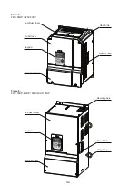
Page 22: ...me 5 240V 25HP 480V 30HP Frame 6 240V 30HP 40HP 480V 40HP 75HP Keypad Terminal Cover Lifting Ring Name Plate Anti Dust Cover Mounting Hole Front Cover Keypad Terminal Cover Heat Sink Name Plate Anti Dust Cover ...

Page 23: ... 20HP 480V 1HP 25HP 240V 25HP 40HP 480V 30HP 75HP 3 5 Removing the Front Cover Before making any wiring connections to the AC Drive the front cover needs to be removed Step 1 Unscrew cover Note 0 5HP 1HP 240V 1HP 2HP 480V models do not use screws Step 2 Remove the terminal cover Step 3 Wire and re install the cover Step 4 Tighten screws ...

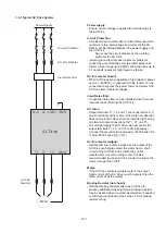
Page 24: ...s will result in AC Drive damage to the semiconductor components Do NOT touch any of the components on the AC Drive control board to prevent damage to the AC Drive by static electricity Refer to the recommended wire size table for the appropriate wire to use The voltage between the power supply and the input of the AC Drive may not exceed 2 Phase to phase voltage drop V 3 resistance of wire Ω km l...

Page 25: ... the motor If the motor run direction does not match AC Drive direction indicator light swap any two terminals connections for T1 T2 and T3 To avoid damaging the AC Drive do not connect the output terminals T1 T2 and T3 to AC input power Connect the ground terminal properly 240V series Rg 100Ω 480V series Rg 10Ω AC line reactor output Optional AC line reactor installed on the output of the AC Driv...

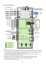
Page 26: ...kΩ 10kΩ Note 6 S S S RS485 S RS485 Terminal 1 2 7 8 Int Transistor Brake Connection Ext Transistor Brake Connection or B1 P Notes 1 Only 240V 0 5 25HP and 480V 1 30HP have a built in braking transistor The braking resistor can be connected directly between P and BR or B1 P and B2 Others require braking unit and resistor See section 3 17 for details 2 Functional Safety input SF and SG should be a n...

Page 27: ...n terminal JP1 Switching NPN position 15 Max output current 60mA 24V Digital signal common terminal JP1 Switching PNP position Analog inputs 10V Built in Power for an external speed potentiometer 10V Max current 20mA AI1 AV1 Multifunctional analog input JP2 selects voltage or current input 0 10V Max current 20mA Input impedance 153KΩ Voltage JP2 in AV1 position Current JP2 in AI1 position AI2 AV2 ...

Page 28: ...layouts may be slightly different Please see table and diagrams below for details on terminal labels and their functions BR L1 L L2 L3 N T1 T2 T3 P Frame 1 Three Phase Models TD400 20P5 13PH TD400 2001 13PH TD400 4001 3PH TD400 4002 3PH AC Drive Terminal Terminal function description L1 L Main power input L2 L3 N T1 AC Drive output connect to U V W terminals of motor T2 T3 P Externally connected b...

Page 29: ... 3PH TD400 4075 3PH Terminal symbol Terminal function description R L1 Main power input S L2 T L3 U T1 AC Drive output connect to U V W terminals of motor V T2 W T3 B1 P Externally connected braking resistor B2 B1 P Externally connected braking unit optional Terminal symbol Terminal function description R L1 Main power input S L2 T L3 U T1 AC Drive output connect to U V W terminals of motor V T2 W...

Page 30: ... T3 3 Connect the output terminals U T1 V T2 W T3 to motor lead wires U T1 V T2 and W T3 respectively 4 Check that the motor rotates forward with a forward run command If it does not swap any 2 output cables to change motor direction 5 DO NOT connect phase correcting capacitors or a LC RC noise filter to the output circuit Example Power Connections AC Drive with dedicated power line AC Drive IM Po...

Page 31: ...resistance of wire Ω km length of line m current 10 3 km 3280 x feet m 3 28 x feet 3 12 Cable Length vs Carrier Frequency The allowable setting of the PWM carrier frequency is also determined by motor cable length and is specified in the following table Cable length between the AC Drive and Motor in m ft 30m 100 30 50 100 165 50 100 166 328 100 329 Recommended carrier frequency allowed Parameter 1...

Page 32: ...uits to minimize noise problems The maximum wiring distance should not exceed 50m 165 ft Shield Twisted Pair Wrap with insulating Tape Ground Shield at AC Drive end ON ONLY DO NOT L ONLY DO NOT Y ONLY DO NOT D ONLY DO NOT O ONLY DO NOT ONLY DO NOT N ONLY DO NOT O ONLY DO NOT T ONLY DO NOT Ground Shield at this end 3 16 AC Drive derating based on Carrier Frequency 100 70 85 90 50 60 2 4 6 8 10 12 1...

Page 33: ...sistor DBR 2015 1 13 6 2400 10 100 10 1500 20 15 Includes Transistor DBR 2015 1 13 6 2400 10 100 10 1500 25 18 5 Note 1 DBR 2025 1 8 4800 10 119 7 2400 30 22 TBU 230 1 DBR 2030 1 6 8 4800 10 117 5 5 3000 40 30 TBU 230 2 DBR 2040 KIT 2 10 3000 10 119 5 5 3000 480V 3Ph 1 0 75 Includes Transistor DBR 4001 C 1 750 150 10 123 120 500 2 1 5 Includes Transistor DBR 4002 C 1 400 150 10 117 120 500 3 2 2 I...

Page 34: ...nning in reverse direction flashing when stopping PARAM LED ON when parameters are displayed KEYS 8 Description RUN RUN AC Drive in Local Mode STOP RESET STOP AC Drive and reset alarms or resettable faults Parameter navigation Up increase parameter or reference value Parameter navigation Down decrease parameter or reference value FWD REV FWD Forward Run REV Reverse Run MODE PROG MODE Switch betwee...

Page 35: ...on At power up the display will show the frequency reference setting all LEDs are flashing Use the keypad potentiometer to adjust set frequency During run operation the display will show the output frequency Actual LED Display A B C D E F G H I J Actual LED Display L n o P q r S t u V Actual LED Display Y _ ...

Page 36: ...oltage class note Displays AC Drive current Displays DC Bus Voltage Displays temperature Displays PID feedback value The displayed digit is set by 12 01 Error display refer to Chapter 7 Troubleshooting and maintenance Analog Current Voltage AI1 AI2 Range 0 1000 Note When power is applied to the drive the display will temporarily flash the input voltage class of that model This display uses the sam...

Page 37: ...irection Illuminated AC Drive is running in forward direction Flashing Forward direction active no run command State Description Reverse LED Off AC Drive in forward direction Illuminated AC Drive is running in reverse direction Flashing Reverse direction active no run command State Description PARAM LED Off Display doesn t show parameter Illuminated Display shows parameter Flashing Fire mode enabl...

Page 38: ...EV command FWD command RUN command REV command Stop command FWD command FWD Indicator REV Indicator REV REV REV REV REV FWD FWD FWD FWD FWD FWD FWD REV REV REV REV Power on Output Frequency Running Stopping Stopped FWD REV Stopped ...

Page 39: ...display will momentarily show the voltage class of the AC Drive Run Frequency Displays the output frequency to the motor Parameters Displays the last parameter accessed The and keys change the parameter number DC Bus Voltage Displays voltage present in the AC Drive s DC Bus Output Voltage note Displays the voltage present at the output terminals of the AC Drive Output Amperage Displays the current...

Page 40: ...aying voltage class the screen will display setting frequency 3 Press MODE PROG to enter program mode The second digit from the left will blink indicating selected digit 4 The Rated Current Motor 1 parameter is Press UP key twice to change flashing digit to Step Key Display 5 Press LEFT key twice to select far right digit 6 Press UP key once to change flashing digit to 7 Press the READ ENTER key t...

Page 41: ...13 Maintenance Parameters Group 14 PLC Parameters Group 15 PLC Monitoring Parameters Group 16 LCD Parameters Group 17 Automatic Tuning Parameters Group 18 Slip Compensation Parameters Group 20 Speed Control Parameters Group 21 Torque and Position Control Parameters Group 22 PM Motor Parameters Parameter Notes 1 Parameter can be changed during running 3 Parameter will not reset to default during a ...

Page 42: ...pad 2 External AI1 Analog Signal Input 3 External AI2 Analog Signal Input 4 External Up Down Frequency 5 Communication Setting Frequency 6 Reserved 7 Pulse Input 1 00 06 Alternative Frequency Command Source 0 UP DOWN on Keypad 1 Potentiometer on Keypad 2 External AI1 Analog Signal Input 3 External AI2 Analog Signal Input 4 External Up Down Frequency 5 Communication Setting Frequency 6 Reserved 7 P...

Page 43: ...m 0 1 Keep Running At Lower Frequency 00 36 PID Lower Frequency Selection 0 Lower Frequency of PID Sleep Mode disable 0 1 0Hz of PID Sleep Mode enable 00 11 Initial Frequency Setpoint range depends on the setting of 01 02 and 01 08 or 01 16 and 01 22 for V F and SLV modes Depends on 22 06 for PMSLV mode 00 12 Frequency upper limit range depends on the setting of 01 02 or 01 16 for V F and SLV mode...

Page 44: ... 14 Input Voltage Setting 240V 55 0 255 0 230 V 8 480V 10 0 510 0 460 01 15 Torque Compensation Time 0 10000 200 ms X X 01 16 Maximum Output Frequency Motor 2 4 8 599 0 50 0 60 0 Hz X X 8 01 17 Maximum Output Voltage Motor 2 240V 0 1 255 0 230 V X X 8 480V 0 2 510 0 460 01 18 Middle Output Frequency 2 Motor 2 0 0 599 0 0 Hz X X 01 19 Middle Output Voltage 2 Motor 2 240V 0 0 255 0 0 V X X 480V 0 0 ...

Page 45: ...r 1 80 300 KVA X X 02 13 Core loss Motor 1 0 0 15 0 KVA X X 02 15 Line to line Resistance Motor 1 1 60000 KVA Ω X X 02 17 Leakage Inductance Motor 1 0 01 200 00 KVA mH X 02 19 No Load Voltage Motor 1 240V 50 240 KVA V X X 480V 100 480 KVA 02 20 No Load Current Motor 2 0 01 600 00 KVA A X X 02 21 Rated Current Motor 2 10 200 of AC Drive rated current KVA A X X 02 22 Rated Rotation Speed Motor 2 0 6...

Page 46: ...n 14 Emergency Stop decelerate to zero and stop 15 External Baseblock Command coast to stop 16 PID Control Disabled 17 Fault Reset 18 Auto Run Mode Enable 19 Speed Search 20 Energy Saving 21 Reset PID integral value to Zero 22 Counter Input 23 Counter reset 24 PLC Input 25 Pulse width modulation measurement S3 only 26 Pulse frequency measure S3 only 27 Local Remote selection 28 Remote mode selecti...

Page 47: ...t 0 During Running 1 Fault Contact Output 2 Frequency Agree 3 Setting Frequency Agree 03 13 03 14 4 Frequency Detection 1 03 13 03 14 5 Frequency Detection 2 03 13 03 14 6 Automatic Restart 7 Momentary AC Power Loss 8 Rapid Stop 9 Base Block 10 Motor Overload Protection OL1 11 Drive Overload Protection OL2 12 Over torque Threshold Level OL3 13 Preset Output Current Reached 14 Brake Control 15 PID ...

Page 48: ...1 0 9999 0 03 23 Pre Set Count 2 0 9999 0 03 24 Output Under Current Detection 0 Invalid 0 1 Valid 03 25 Output Under Current Detection Level 0 999 9 0 1 A 03 26 Output Under Current Detection Delay Time 0 0 655 34 0 01 s 03 27 UP DOWN Frequency Hold Adjust Selection 0 Hold last set frequency when stopped 1 Set frequency to 0 when stopped 2 Allow speed changes from last set frequency when stopped ...

Page 49: ...5 AI1 Slope 0 Positive 0 1 Negative 04 06 AI2 Signal Scanning and Filtering Time 0 00 2 00 0 03 s 04 07 AI2 Gain 0 0 1000 0 100 04 08 AI2 Bias 0 100 0 0 04 09 AI2 Bias Selection 0 Positive 1 Negative 0 04 10 AI2 Slope 0 Positive 0 1 Negative 04 11 Analog Output AO Mode 0 Output Frequency 0 1 Frequency Command 2 Output Voltage 3 DC Bus Voltage 4 Output Current 04 12 AO Gain 0 0 1000 0 100 04 13 AO ...

Page 50: ...z 1 Note 05 14 Preset Speed 13 0 00 599 00 5 Hz 1 Note 05 15 Preset Speed 14 0 00 599 00 5 Hz 1 Note 05 16 Preset Speed 15 0 00 599 00 5 Hz 1 Note 05 17 Preset Speed 0 Acc time 0 1 6000 0 10 s 05 18 Preset Speed 0 Dec time 0 1 6000 0 10 s 05 19 Preset Speed 1 Acc time 0 1 6000 0 10 s 05 20 Preset Speed 1 Dec time 0 1 6000 0 10 s 05 21 Preset Speed 2 Acc time 0 1 6000 0 10 s 05 22 Preset Speed 2 De...

Page 51: ... 10 s Group 06 Automatic Program Operation Param Parameter Name Setting Range Default Unit Control mode Notes V F SLV PMSLV 06 00 Auto Run Mode Selection 0 Disabled 0 X 1 Execute a single cycle operation mode Restart speed is based on the previous stopped speed 2 Execute continuous cycle operation mode Restart speed is based on the previous stopped speed 3 After the completion of a single cycle th...

Page 52: ... Note 06 15 Frequency Setting Operation Stage 15 0 00 599 00 0 Hz X 1 Note 06 16 Operation Time Setting Speed Stage 0 0 0 6000 0 0 s X 1 06 17 Operation Time Setting Speed Stage 1 0 0 6000 0 0 s X 1 06 18 Operation Time Setting Speed Stage 2 0 0 6000 0 0 s X 1 06 19 Operation Time Setting Speed Stage 3 0 0 6000 0 0 s X 1 06 20 Operation Time Setting Speed Stage 4 0 0 6000 0 0 s X 1 06 21 Operation...

Page 53: ...everse 0 X 06 39 Operation Direction Speed Stage 7 0 Stop 1 Forward 2 Reverse 0 X 06 40 Operation Direction Speed Stage 8 0 Stop 1 Forward 2 Reverse 0 X 06 41 Operation Direction Speed Stage 9 0 Stop 1 Forward 2 Reverse 0 X 06 42 Operation Direction Speed Stage 10 0 Stop 1 Forward 2 Reverse 0 X 06 43 Operation Direction Speed Stage 11 0 Stop 1 Forward 2 Reverse 0 X 06 44 Operation Direction Speed ...

Page 54: ...DC Injection Braking Time 0 0 25 5 0 5 s 07 09 Stop Mode Selection 0 Deceleration to Stop 0 1 Coast to Stop 2 DC Braking Stop in All Fields 3 Coast to Stop with Timer 07 10 Speed Search Mode Selection 0 Normal Start 0 X 1 Execute Speed Search Once 2 Speed Search Start 07 11 DC Injection Braking Start Time 0 00 100 00 0 00 s 07 13 Low Voltage Detection Level 240V 150 300 190 V 480V 250 600 380 07 1...

Page 55: ...200 100 X X 07 39 PM Motor Speed Search Function Short Circuit Braking Time 0 00 100 00 0 Sec X X 07 40 PM Motor Speed Search Function DC Injection Braking Time 0 00 100 00 0 Sec X X 07 45 Terminal Stop Display 0 Enabled 1 Disabled 0 Group 08 Protection Parameters Param Parameter Name Setting Range Default Unit Control mode Notes V F SLV PMSLV 08 00 Stall Prevention Function xxx0b Stall prevention...

Page 56: ...08 10 Output Phase Loss Protection 0 Disable 1 Enable 0 08 13 Over Torque Detection 0 Over Torque Detection is Disabled 0 1 Start detection when reaching the set frequency 2 Start detection during running 08 14 Over Torque Action 0 Decelerate to Stop when Over Torque is Detected 0 1 Display Warning when Over Torque is Detected Continue operation 2 Coast to Stop when Over Torque is Detected 08 15 L...

Page 57: ...er Power Off 1 Reset after Terminal Removed 0 08 50 Input Terminal Type xxx0b S6 A Contact xxx1b S6 B Contact 0000b 08 51 Fire Mode Motor Speed Source 0 Fire Mode Speed 08 52 1 PID Control 2 AI2 0 08 52 Fire Mode Motor Speed 0 00 100 00 100 00 08 53 Fire Mode PID Feedback Loss Detection Level 0 100 0 08 54 Fire Mode PID Feedback Loss Detection Time 0 0 10 0 1 0 08 55 Fire Mode PID Feedback Loss De...

Page 58: ...ommunication Data Bit Selection 0 8 Bit Data 0 3 note 1 7 Bit Data 09 06 Communication Error Detection Time 0 0 25 5 0 S 3 note 09 07 Fault Stop Selection 0 Deceleration to Stop By Deceleration Time 1 3 3 note 1 Coast to Stop 2 Deceleration to Stop By Deceleration Time 2 3 Continue 09 08 Communication Error Threshold 0 20 1 3 note 09 09 Waiting Time 5 65 5 ms 3 note 09 10 BACNET Device Instance Nu...

Page 59: ...00 1 1 10 06 Integral Time I 0 00 100 00 1 s 1 10 07 Differential Time D 0 00 10 00 0 s 1 10 08 PID Offset 0 Positive 1 Negative 0 10 09 PID Bias 0 109 0 1 10 11 PID Feedback Loss Detection Selection 0 Disable 1 Warning 2 Fault 0 1 10 12 PID Feedback Loss Detection Level 0 100 0 10 13 PID Feedback Loss Detection Delay Time 0 0 25 5 1 s 10 14 PID Integral Limit 0 0 100 0 100 1 10 15 PID Integrator ...

Page 60: ...quency 00 00 599 00 30 Hz Note 10 40 PID Sleep Compensation Frequency 0 Disable 1 Enable 0 10 41 Differential Mode Enable 0 Disable 1 Differential PID Mode 0 10 47 Fire Mode Proportional Gain P 0 00 10 00 1 00 10 48 Fire Mode Integral Time I 0 00 100 00 1 00 s 10 49 Fire Mode Differential Time D 0 00 10 00 0 00 s Note 10 50 Derivative Filter 1 250 4 10 51 PID Integrator Tolerance 0 100 0 10 52 Acc...

Page 61: ...idth 0 0 25 5 1 Hz 11 12 Manual Energy Saving Gain V F 0 100 80 X X 11 13 OV Prevention Selection 0 Disable 1 OV Prevention Mode 1 2 OV Prevention Mode 2 3 OV Prevention Mode 3 0 X X 11 14 OV Prevention Level 240V 200V 400V 370 V X X 480V 400V 800V 740 11 17 Accel Decel Gain 0 1 10 0 1 X X 11 18 Manual Energy Savings Frequency 0 0 599 0 0 Hz X X 11 19 Automatic Energy Saving Function 0 Automatic e...

Page 62: ...Disabled when the Operation Command is not Provided by Operator 1 1 Stop Key is Enabled when the Operation Command is not Provided by Operator 11 59 Oscillation Prevention Gain 1 0 00 2 50 0 X X note 11 60 Upper Limit of Oscillation Prevention 1 1 100 100 X X note 11 61 Time Parameter of Oscillation Prevention 1 0 100 0 X X 11 62 Oscillation Prevention 0 Mode 1 1 X X 1 Mode 2 2 Mode 3 11 63 Strong...

Page 63: ...y Unit Setting LED 0 xxxxx no unit 0 6 1 xxxPb pressure 2 xxxFL flow 12 03 Line Speed Display LED 0 60000 1500 1800 RPM 1 6 12 04 Modes of Line Speed Display LED 0 Display AC Drive Output Frequency 0 1 6 1 Display Line Speed as integer xxxxx 2 Display Line Speed with the First Decimal Place xxxx x 3 Display Line Speed with the Second Decimal Place xxx xx 4 Display Line Speed with the Third Decimal...

Page 64: ...ent q axis current A X 4 12 29 Motor Excitation Current Id Display the current d axis current A X 4 12 36 PID Input Display input error of the PID controller PID target value PID feedback 100 corresponds to the maximum frequency set by 01 02 or 01 16 4 12 37 PID Output Display output of the PID controller 100 corresponds to the maximum frequency set by 01 02 or 01 16 4 12 38 PID Setting Display th...

Page 65: ...ion 60Hz 220V 380V 3 2 wire initialization 50Hz 240V 480V 4 2 wire initialization 60Hz 240V 480V 5 2 wire initialization 50Hz 220V 415V 6 2 wire initialization 60Hz 230V 400V 7 2 wire initialization 50Hz 220V 440V 8 2 wire initialization 60Hz 220V 440V 1112 PLC initialization RESET KVA 13 10 Parameter Password Function 2 0 9999 0 13 51 Hour Meter Reset 0 Do not reset operation time 1 Reset operati...

Page 66: ... C8 Set Value 0 65534 0 14 24 AS1 Set Value 1 0 65534 0 14 25 AS1 Set Value 2 0 65534 0 14 26 AS1 Set Value 3 0 65534 0 14 27 AS2 Set Value 1 0 65534 0 14 28 AS2 Set Value 2 0 65534 0 14 29 AS2 Set Value 3 0 65534 0 14 30 AS3 Set Value 1 0 65534 0 14 31 AS3 Set Value 2 0 65534 0 14 32 AS3 Set Value 3 0 65534 0 14 33 AS4 Set Value 1 0 65534 0 14 34 AS4 Set Value 2 0 65534 0 14 35 AS4 Set Value 3 0 ...

Page 67: ...Value 2 Mode7 0 9999 0 15 12 T7 Current Value 1 0 9999 0 15 13 T7 Current Value 2 Mode7 0 9999 0 15 14 T8 Current Value 1 0 9999 0 15 15 T8 Current Value 2 Mode7 0 9999 0 15 16 C1 Current Value 0 65535 0 15 17 C2 Current Value 0 65535 0 15 18 C3 Current Value 0 65535 0 15 19 C4 Current Value 0 65535 0 15 20 C5 Current Value 0 65535 0 15 21 C6 Current Value 0 65535 0 15 22 C7 Current Value 0 65535 ...

Page 68: ...1 16 03 Display Unit 0 39999 Determine the display way and unit of frequency commands 0 Frequency display unit is 0 01Hz 1 Frequency display unit is 0 01 2 Frequency display unit is rpm 3 39 Reserved 40 9999 Users specify the format Input 0XXXX represents display of XXXX at 100 10001 19999 Users specify the format Input 1XXXX represents display of XXX X at 100 20001 29999 Users specify the format ...

Page 69: ... Tuning Parameters Param Parameter Name Setting Range Default Unit Control Mode Notes V F SLV PMSLV 17 00 Automatic Tuning Mode 0 Rotation Auto tuning 1 Static Auto tuning 2 Stator Resistance Measurement 3 Reserved 4 Loop Tuning 5 Rotation Auto tuning Combination item 4 2 0 6 Static Auto tuning Combination item 4 2 1 V F 2 SLV 6 X note 17 01 Motor Rated Output Power 0 00 600 00 KVA KW X note 17 02...

Page 70: ...tor will turn during Rotation Auto Tuning 17 01 17 02 17 05 The default value of this parameter will be changed according to the AC Drive capacity It is recommended that HD ND mode 00 27 be selected first before motor performs auto tuning 17 08 and 17 09 Do not adjust contact factory before making any changes to these parameters Group 18 Slip Compensation Parameters Param Parameters Setting Range ...

Page 71: ...000 0 500 0 004 Sec X 20 09 Speed Observer Proportional P Gain1 0 00 2 55 0 61 X X 1 20 10 Speed Observer Integral I Time 1 0 01 10 00 0 05 Sec X X 1 20 11 Speed Observer Proportional P Gain2 0 00 2 55 0 61 X X 1 20 12 Speed Observer Integral I Time 2 0 01 10 00 0 06 Sec X X 1 20 13 Speed Feedback 1 Low pass Filter Time Constant 1 1000 4 ms X X 20 14 Speed Feedback 2 Low pass Filter Time Constant ...

Page 72: ...ductance 0 01 300 00 10 mH X X 22 16 PM Motor Q axis Inductance 0 01 300 00 10 mH X X 22 18 Flux Weakening Limit 0 100 0 X X 22 21 PM Motor Tuning 0 PM Motor Tuning is not Active 1 Parameter Auto tune 0 X X 22 22 PM Motor Tuning Fault 0 No Faults 5 Loop Adjustment Timed Out 7 Other Motor Tuning Errors 9 Current Abnormal during Loop Adjustment 0 X X 4 22 23 PMSLV acceleration time 0 1 10 0 1 Sec X ...

Page 73: ...m value of 11 01 in HD mode Other control modes 20P5 1 150 150 5 16 16 2001 5 16 16 2002 2 150 150 5 16 16 2003 5 16 16 2005 5 16 16 27P5 3 150 150 5 16 16 2010 5 16 16 2015 4 110 110 5 16 16 2020 5 16 16 2025 5 100 80 5 8 12 2030 6 100 80 5 8 12 2040 5 8 12 4001 1 150 150 5 16 16 4002 5 16 16 4003 2 150 150 5 16 16 4005 5 16 16 47P5 3 150 150 5 16 16 4010 5 16 16 4015 5 16 16 4020 4 110 110 5 16 ...

Page 74: ...18 00 Low speed slip compensation 20P5 200 0 001 10 YES 1 2001 2002 200 0 001 10 YES 1 2003 2005 27P5 200 0 001 10 YES 1 2010 2015 200 0 002 15 YES 1 2020 2025 160 0 002 20 YES 0 7 2030 160 0 004 20 YES 0 7 2040 4001 200 0 001 10 YES 1 4002 4003 200 0 001 10 YES 1 4005 47P5 200 0 001 10 YES 1 4010 4015 4020 200 0 002 15 YES 1 4025 4030 160 0 002 20 YES 0 7 4040 160 0 004 20 YES 0 7 4050 4060 4075 ...

Page 75: ...er Group 1 If desired select a V F curve 01 00 based on your motor and application Perform a stationary auto tune 17 00 1 if the motor cable is longer than 50m 165ft see parameter 17 00 for details 00 00 2 Sensorless Vector Control without encoder SLV mode can provide greater regulation of motor speed but requires tuning of the drive to individual motor SLV mode cannot run multiple motors from one...

Page 76: ...t and stop the AC Drive and select motor direction There are three different types 2 wire operation 3 wire operation and 2 wire self holding latching mode See instruction details for parameter 00 04 for more information 00 02 00 03 2 Communication control The AC Drive is controlled by the RS 485 port Refer to parameter Group 9 for communication setup Example Command String in hexadecimal 01 06 25 ...

Page 77: ...lose Momentary switch Stop Command Off Stop Run Command On Run JP1 Note 00 04 is valid when run command is set to external mode by 00 02 00 03 1 2 Wire Operation Mode Set 00 04 to 0 or 1 first before setting 03 00 S1 terminal selection to 0 and 03 01 S2 terminal selection to 1 Terminal S1 Terminal S2 Operation Open Open Stop AC Drive Closed Open Run Forward Open Closed Run Reverse Closed Closed St...

Page 78: ...rnate frequency Use analog reference from analog input AI1 or AI2 to set the frequency reference as shown below Refer to parameter 04 00 to select the signal type JP2 JP3 External signal type selection 0 20mA 4 20mA Analog signal 0 10VDC 2 10VDC Analog signal V AGND 2KΩ AI1 AI2 Main Frequency Reference Command voltage or current input 10 Main Frequency Reference Command voltage or current input Pa...

Page 79: ...ions 25 and 26 S3 GND 0V Serial pulse input Input resistance 3 89 KΩ Specifications Low Input Level 0 0 to 0 5 V High Input Level 4 0 to 13 5 V Duty cycle ON OFF 30 to 70 Pulse Input Frequency Range 50 to 25 KHz 00 07 Main and Alternative Frequency Command Modes Default 0 Range 0 Main reference frequency 1 Main frequency alternative frequency When set to 0 the reference frequency is set by the mai...

Page 80: ...equency Default KVA Range 0 01 599 00 Hz Upper Limit Frequency range depends on the setting of 01 02 or 01 16 for V F and SLV modes PMSLV mode depends on setting of 22 06 00 13 Lower Limit Frequency Default 0 Range 0 01 598 99 Hz Lower Limit Frequency range depends on the setting of 01 08 or 01 22 for V F and SLV modes PMSLV mode depends on setting of 22 06 The AC Drive will display the SE01 error...

Page 81: ...eration Deceleration Default Value 240V Series 480V Series 1 10HP 1 15HP 10s 15 20HP 20 30HP 15s 30 40HP 40 75HP 20s 00 15 x set frequency Min Starting Freq 00 11 Actual acceleration time 00 14 x set frequency Min Starting Freq 00 11 Max Output Freq 00 12 Actual deceleration time Max Output Freq 00 12 Acceleration and deceleration times are represented by the three most significant high order digi...

Page 82: ...og Deceleration Time Default Range 0 1 25 5 Sec The JOG function is operational by using the multi function input terminals S1 to S6 and setting the relevant parameters 03 00 03 05 to 6 JOG FWD or 7 JOG REV Refer to parameter group 3 Notes To activate the JOG FWD function set any of the multi function input terminals S1 to S6 to 6 To activate the JOG REV function set any of the multi function inpu...

Page 83: ...Class 25HP and above and 480V class 30HP and above Frames 5 and 6 Select V F curve Group 1 and enter motor data Group 2 to match your application In Heavy Duty mode the maximum output frequency is 599Hz for all control modes except for SLV mode Sensorless Vector Open Loop Vector Mode where the maximum output frequency is limited based on the AC Drive rating See table below Horsepower Carrier Frequ...

Page 84: ...zing see parameter 13 08 00 35 Minimum Frequency Detection Default 0 Range 0 Alarm 1 Keep Running at Lower Frequency 00 35 0 Alarm When output frequency falls below the minimum frequency 01 08 display shows STP0 alarm 00 35 1 Keep Running at Lower Frequency When the output frequency falls below the minimum frequency the AC Drive will keep running at minimum frequency 00 36 PID Lower Frequency Sele...

Page 85: ...V F curves are selected Note Parameters 01 02 to 01 09 and 01 12 to 01 13 are only editable when 01 00 FF 01 16 to 01 25 for motor 2 V F curve selection Consider the following items as the conditions for selecting a V F pattern 1 The voltage and frequency characteristic of motor 2 The maximum speed of motor 01 03 Vmax 01 05 Vmid2 01 07 Vmid1 01 09 Vmin 01 08 01 06 01 04 01 02 V Hz 599 00 Output Vo...

Page 86: ...5 4 100 V 01 14 17 5 25 3 3 3 6 5 Variable Torque 2 6 60Hz Variable Torque 3 Hz 0 7 60 1 5 30 6 100 01 14 17 5 25 3 3 3 6 V 7 Variable Torque 4 01 00 Specification V F curve 8 50Hz Low Starting Torque Hz 0 9 50 1 3 2 5 8 100 01 14 7 7 3 3 65 3 7 V 9 High Starting Torque A 60Hz Low Starting Torque Hz 100 0 B 60 1 5 3 A 01 14 7 7 3 3 65 3 7 V B High Starting Torque C 90Hz Hz 100 90 C 60 0 1 5 3 V 3 ...

Page 87: ...25 4 100 17 5 25 01 14 3 4 3 V 5 Variable Torque 2 6 60Hz Variable Torque 3 Hz 0 7 60 1 5 30 6 100 17 5 25 01 14 3 4 3 V 7 Variable Torque 4 01 00 Specification V F curve 8 50Hz Low Starting Torque Hz 0 9 50 1 3 2 5 8 100 6 6 6 9 01 14 3 5 3 4 V 9 High Starting Torque A 60Hz Low Starting Torque Hz 100 0 B 60 1 5 3 A 6 6 6 9 01 14 3 5 3 4 V B High Starting Torque C 90Hz Hz 100 90 C 60 0 1 5 3 01 14...

Page 88: ...0 3 85 18 2 01 14 26 2 V 5 Variable Torque 2 6 60Hz Variable Torque 3 Hz 0 7 60 1 5 30 6 100 3 85 18 2 01 14 26 2 V 7 Variable Torque 4 01 00 Specification V F curve 8 50Hz Low Starting Torque Hz 0 9 50 1 3 2 5 8 100 3 85 4 1 01 14 6 95 7 25 V 9 High Starting Torque A 60Hz Low Starting Torque Hz 100 0 B 60 1 5 3 A 3 85 4 1 01 14 6 95 7 25 V B High Starting Torque C 90Hz Hz 100 90 C 60 0 1 5 3 01 1...

Page 89: ...08 The SE03 V F curve tuning error is displayed when the frequency values are set incorrectly Note Custom curves F and FF use the values from curve 0 for 50Hz or 1 for 60Hz as a baseline If any changes are made to the custom curve from this baseline all curve parameters must be updated with appropriate data 01 02 to 01 13 for motor 1 and 01 16 to 01 25 for motor 2 Important Improper V F curve sele...

Page 90: ... 02 Vmid1 Fmid1 01 06 Fmin 01 08 Custom V F Curve Torque Boosting The value for maximum output voltage of the motor 1 01 03 and the value for base output voltage of the motor 01 13 will depend on the setting of 13 08 which sets the value of voltage upon initialization When the control mode is changed in parameter 00 00 01 08 Fmin and 01 09 Vmin will be automatically changed to the default setting ...

Page 91: ...rameters 02 19 or 17 04 to reduce the voltage at no load operation Motor jitter can be reduced by lowering the no load voltage which will increase the current Output Voltage V Vmax Vmid2 Vmin Fmid2 01 04 Fbase 01 12 Fmax 01 02 Vmid1 Fmid1 01 06 Fmin 01 08 Torque Boost Compensation 01 10 Torque Boost Default 0 5 Range 0 0 2 0 01 11 Torque Boost Mode Range 0 Mode 0 Normal 1 Mode 1 High Speed Torque ...

Page 92: ... continued operation may cause motor to overheat Base frequency 100 Output Voltage Torque Increase Torque Decrease 01 10 01 14 Input Voltage Setting Default 230 or 400 Range 240V 155 0 255 0 V 480V 310 0 510 0 V 01 12 Base frequency of motor 1 Default 50 0 60 0 Range 4 8 599 0 Hz 01 13 Base output voltage of motor 1 Default 230 or 400 Range 240V 0 0 255 0 V 480V 0 0 510 0 V Important Do not adjust...

Page 93: ... 0 255 0 V 480V 0 0 510 0 V 01 24 Base frequency of motor 2 Default 50 0 60 0 Range 4 8 599 0 Hz 01 25 Base voltage of motor 2 Default 230 or 400 Range 240V 0 0 255 0 V 480V 0 0 510 0 V 01 26 V F Curve of Motor 2 Default F Range 0 FF Note 1 Motor 2 V F curve is initially the same as V f curve of Motor 1 Select the V F curve for motor 2 using 01 26 Note 2 Parameters 01 16 01 25 are changed when a n...

Page 94: ...0 1 In most cases no adjustment is required after performing an auto tune except when using the AC Drive in special applications e g machine tool positioning etc Please refer to parameter group 22 for permanent magnet motor parameters 02 00 Motor no load current Value is calculated based on the motor rated frequency 17 05 and motor rated current 17 02 02 01 Motor rated current The motor rated curr...

Page 95: ...f parameter 02 09 changes the motor leakage inductance of parameter 02 17 and motor mutual inductance of parameter 02 18 4 It is required to refer to the actual no load voltage of parameter 12 19 to tune the motor excitation current parameter 02 09 Changing the excitation current affects the no load voltage fluctuation adjust parameter 02 09 to a value so the output voltage matches the no load vol...

Page 96: ...Range 4 8 599 0 Hz 02 26 Number of Motor Poles of Motor 2 Default 4 Range 2 16 02 32 Line to line Resistance of motor 2 Default Range 0 001 60 000 Ω 02 33 Proportion of Motor Leakage Inductance 1 Default KVA Range 0 1 15 0 02 15 Motor line to line resistance Y equivalent model of an induction motor 02 19 No load motor voltage Parameter determines the rated flux during motor s rated rotation in SLV...

Page 97: ...the motor to run normally Leakage inductance proportion setting depends on the motor rating Lr LlKg ξ 02 34 Motor Slip Frequency Default KVA Range 0 1 20 0 Hz Normally it is not required for this parameter to be adjusted but can be set manually The default value of motor slip is set to 1 Hz Motor slip is obtained from the nameplate Take 60Hz 4 pole motor for example synchronous speed Rated speed i...

Page 98: ... decelerate to zero and stop 15 External Baseblock Command coast to stop 16 PID Control Disabled 17 Fault Reset 18 Auto Run Mode Enable 19 Speed Search 20 Energy Saving 21 Reset PID integral value to Zero 22 Counter Input 23 Counter reset 24 PLC Input 25 Pulse width modulation measurement S3 only 26 Pulse frequency measure S3 only 27 Local Remote selection 28 Remote mode selection 29 Jog Frequency...

Page 99: ...og run command RJOG ON Reverse operation in jog mode 00 18 O O O 8 UP frequency increasing command UP command ON Increase output frequency Function only active when Up Down DOWN command is programmed O O O 9 DOWN frequency decreasing command DOWN command ON Decrease output frequency Up Down Function only active when ON command is programmed O O O 10 Acceleration deceleration time selection Acc Dec...

Page 100: ...F Frequency and operation command will be determined according to the setting of parameter 00 02 and 00 05 O O O 28 Remote Mode Selection Remote Mode Sel ON RS 485 communication control active OFF Control circuit terminal active O O O 29 Jog Frequency Selection JOG Freq sel ON Jog Frequency Active O O O 33 DC Braking DC Brake Command ON DC braking active O O O 34 Speed Search 2 From Frequency Comm...

Page 101: ...5 0 1 1 1 1 Frequency command 15 05 16 16 1 1 Jog frequency command 00 18 0 OFF 1 ON Ignore 1 Jog frequency terminal has a higher priority than multi speed reference 1 to 4 2 When parameter 00 05 0 frequency reference input digital operator multi speed frequency 1 will be set by 05 01 frequency reference setting1 When parameter 00 05 1 frequency reference input control circuit terminal multi speed...

Page 102: ...s UP DOWN frequency command follows the standard acceleration and deceleration times SE02 DI terminal error will be displayed when When only one UP or DOWN command is programmed for the digital inputs When DOWN command and Inhibit Acceleration deceleration command are active simultaneously When UP command and Inhibit Acceleration deceleration command are active simultaneously For an example of UP ...

Page 103: ...of inhibit Acceleration deceleration function please refer to figure below The frequency reference value is saved when the acceleration deceleration inhibit command is active and the frequency reference value is saved even when powering down the AC Drive Power Supply Forward Run Inhibit Acc Dec Command Frequency Reference Output Frequency ON ON OFF ON OFF ON OFF ON OFF ON Hold Hold time time time ...

Page 104: ...to a stop and the AC Drive remains in the stop condition During acceleration When an external base block command is activated the keypad displays BBn BaseBlock Sn indicating the AC Drive output is turned off n indicates the digital input number 1 6 Upon removing the base block signal the motor will run at the frequency reference If speed search from frequency reference is active the AC Drive outpu...

Page 105: ...3 0X 24 PLC Input When the inputs are set to PLC Input the AC drive input operation must be programmed using the TD LINK software The multi function inputs will function in accordance to the ladder logic programming downloaded to the AC Drive from the TD LINK software Any S terminal input or combination of inputs can be set to PLC function simultaneously Note When writing PLC program to AC drive t...

Page 106: ...ith speed control 03 02 26 Pulse input frequency 03 32 100 0 1000 0 pulse input gain setting AC Drive reference frequency Pulse input frequency x 03 28 Hz reference frequency limit is the AC Drive frequency upper limit Example 1 Pulse input frequency is 20Hz frequency upper limit is 50Hz 00 12 50 00 and 03 32 100 0 AC Drive reference frequency is 20 00Hz Example 2 Pulse input frequency is 50Hz fre...

Page 107: ...nication RS 485 source for frequency reference and operation command In Remote mode indicators of SEQ and REF are on you can use terminals AI1 and AI2 to control the frequency command and use terminals S1 and S2 or communication terminal RS 485 to control the operation command Input1 Mode Frequency Reference Run Stop Command Source ON Communication Frequency reference and run stop command control ...

Page 108: ...with parameter 08 48 When input is active disables all AC Drive warning and hardware protections This function is commonly used in commercial applications where the AC Drive controls an exhaust fan and needs run to destruction in case of a fire 03 0X 48 KEB acceleration When input is active enables KEB Kinetic Energy Braking to accelerate back to the preset frequency after braking Refer to the par...

Page 109: ...xxb S4 B contact 03 10 Multi function terminal S5 S6 type selection Default 0000b Range xxx0b S5 A contact xxx1b S5 B contact xx0xb S6 A contact xx1xb S6 B contact Parameter 03 09 and 03 10 selects the digital input type between a normally open and a normally closed switch contact 03 0X 66 PID control disabled 03 0X 68 External Fault Activating the external fault input will turn off the AC Drive o...

Page 110: ...nge is the setting value of 03 14 6 Automatic Restart 7 Momentary AC Power Loss 8 Rapid Stop 9 Base Block 10 Motor Overload Protection OL1 11 Drive Overload Protection OL2 12 Over Torque Threshold Level OL3 13 Preset Output Current Reached 14 Brake Control 15 PID Feedback Signal Loss 16 Single Pre set Count 03 22 03 23 17 Dual Pre set Count 03 22 03 23 18 PLC Status Indicator 00 02 19 PLC Control ...

Page 111: ...on OL1 Invalid DO Func Reserved O O O 11 Drive Overload Protection OL2 Invalid DO Func Reserved O O O 12 Over Torque Threshold Level OL3 Over Torque ON Over torque detection is ON O O O 13 Preset Output Current Reached Current Agree ON When output current 03 15 is ON O O O 14 Brake Control Invalid DO Func ON Mechanical braking release frequency OFF Mechanical braking run frequency O O O 15 PID Fee...

Page 112: ...equency falls below frequency detection level Refer to Functions of Multi function Digital Output table for the operation of frequency detection 03 1X 6 Automatic restart Output is active during an auto restart operation 03 1X 7 Momentary AC power loss Output is active during a momentary AC power loss 03 1X 8 Rapid Stop Output is active during a rapid stop 03 1X 9 Baseblock B B Output is active wh...

Page 113: ...n output current 03 25 for the time specified in 03 26 Relay OFF When output current 03 25 for the time specified in 03 26 03 1X 59 Overheat Detection Relay ON When AC drive temperature is 08 46 Relay OFF When AC drive temperature is 08 47 03 1X 19 PLC control contact Output is controlled by the PLC logic 03 1X 20 Zero speed Output is active during zero speed when output frequency minimum output f...

Page 114: ...ON OFF FWD REV 03 14 03 14 Freq Reference Output Frequency Frequency Agree Signal ON Freq Reference Output is active when the output frequency falls within the frequency reference minus the frequency detection width 03 14 Any of the digital outputs function 03 11 03 12 or 03 32 can be set to 2 Frequency agree Set frequency agree time time ON OFF FWD REV 03 14 Output Frequency Setting Frequency Agr...

Page 115: ...Output frequency detection 1 Output frequency detection 2 OFF OFF ON ON 03 14 03 14 03 13 03 13 03 13 03 13 time time Output Frequency Output Frequency Detection 2 Signal ON Output is active when the output frequency is below the frequency detection level 03 13 frequency detection width 03 14 and turns off when the output frequency falls below frequency detection level Any of the digital outputs f...

Page 116: ... Hz 03 18 Mechanical Braking Set Level Default 0 Range 0 00 20 00 Hz When 03 11 14 when the output frequency is greater or equal to the value set in 03 18 Brake Set Level during acceleration the relay output will activate When 03 11 14 when the output frequency falls below the value set in 03 17 Brake Release Level during deceleration the relay output will de activate When 03 18 03 17 the followin...

Page 117: ... 03 20 Internal External Multi function Input Terminal Default 0 Range 0 63 03 21 Action to Set Internal Multi function Input Terminals Default 0 Range 0 63 03 22 Pre set Count 1 Default 0 Range 0 9999 03 23 Pre set Count 2 Default 0 Range 0 9999 03 24 Output Under Current Detection Default 0 Range 0 Invalid 1 Valid 03 25 Output Under Current Detection Level Default 0 1 Range 0 999 9 A 03 26 Outpu...

Page 118: ...cy reference from before deceleration is stored When run command is applied the output frequency will ramp up to the previously stored frequency reference Adjustments to frequency reference can be made at any time during run but before the set frequency is reached 03 31 Pulse Frequency Default 1000 Range 50 25000 Hz 03 32 Pulse Input Gain Default 100 Range 0 0 1000 0 03 33 Pulse Input Bias Default...

Page 119: ... OFF ON O OFF OFF ON N OFF OFF ON 2Sec T H T Hz z T Hz Upper frequency limit Ac Actual output frequency t Actual output frequency u Actual output frequency a Actual output frequency l Actual output frequency Actual output frequency o Actual output frequency u Actual output frequency t Actual output frequency p Actual output frequency u Actual output frequency t Actual output frequency Actual outpu...

Page 120: ...ime Default 0 03 Range 0 00 2 00 Positive 04 07 AI2 Gain Default 100 Range 0 0 1000 0 04 08 AI2 Bias Default 0 Range 0 100 0 04 09 AI2 Bias Selection Default 0 Range 0 Positive 1 Negative 04 10 AI2 Slope Default 0 Range 0 Positive 1 Negative 04 Analog Signal Inputs Analog Output Descriptions ΔH1 frequency increase during acceleration t1 Multi function input active time during acceleration ΔH2 freq...

Page 121: ...ate gain and bias parameter associated with it Analog input signal AI1 can be adjusted with parameter 04 02 and 04 03 Analog input signal AI2 can be adjusted with parameter 04 07 and 04 08 Refer to figure below 10V AI 1 AI 2 GND 10V 0 10V 10V 10V 0 10V 0 20mA 4 20mA 2 10V I V SW2 04 00 Level Selection 04 02 Gain 04 03 Bias 04 00 Level Selection 04 07 Gain 04 08 Bias Related Parameters Gain setting...

Page 122: ...ut Unfiltered signal Filtered signal Filter time constant 04 01 63 100 t 04 11 Analog Output AO Mode Default 0 Range 0 Output frequency 1 Frequency command 2 Output voltage 3 DC voltage 4 Output current 04 12 AO gain Default 100 Range 0 0 1000 0 04 13 AO bias Default 0 Range 0 0 100 0 04 14 AO Bias Selection Default 0 Range 0 Positive 1 Negative 04 15 AO Slope Default 0 Range 0 Positive 1 Negative...

Page 123: ...alog output 10V matches 100 of the selected analog output signal 04 11 for AO Bias Use parameter 04 13 to adjust the bias for AO Adjust the bias so that the analog output 0V matches 0 of the selected analog output signal 04 11 for AO F Gain Function The F Gain function offers the ability to use a single frequency reference set by a master potentiometer to more than one AC Drive The master frequenc...

Page 124: ...0 Preset Speed 9 5 05 11 Preset Speed 10 5 05 12 Preset Speed 11 5 05 13 Preset Speed 12 5 A B C 50Hz 100Hz 200Hz A B C Ratio C Ratio A Ratio B Frequency upper limit Hz Analog Input Signal Master 04 25 AO Voltage Auto Tuning Default 0 Range 0 Disable 1 Enable Parameter 04 25 can be used to compensate for innacuracies in the analog output These may be caused by voltage drop or impedance mismatch be...

Page 125: ...celeration time 10 05 22 Preset Speed 2 Deceleration time 10 05 23 Preset Speed 3 Acceleration time 10 05 24 Preset Speed 3 Deceleration time 10 05 25 Preset Speed 4 Acceleration time 10 05 26 Preset Speed 4 Deceleration time 10 05 27 Preset Speed 5 Acceleration time 10 05 28 Preset Speed 5 Deceleration time 10 05 29 Preset Speed 6 Acceleration time 10 05 30 Preset Speed 6 Deceleration time 10 05 ...

Page 126: ... is set to 1 In this example the following parameters are set 00 02 1 External Terminal Operation 00 04 1 Operation Mode Run Stop Forward Reverse 03 00 0 Terminal S1 Run Stop 03 01 1 Terminal S2 Reversal Stop 03 02 2 Terminal S3 Preset Speed 1 03 03 3 Terminal S4 Preset Speed 2 03 03 4 Terminal S5 Preset Speed 3 If the run command is cycled on and off acceleration and deceleration time a f is calc...

Page 127: ...mmand 2 Speed Command 3 Speed Command 4 Speed Command 5 06 03 06 01 06 04 05 01 On Off Off Off Off On On Off Off Off Terminal S5 19 20 21 22 23 24 25 26 27 28 19 20 in sec 05 17 x 05 01 05 19 x 05 02 05 01 05 21 x 05 02 06 01 01 02 01 02 01 02 a b c 05 24 x 05 01 05 02 05 26 x 05 02 05 25 x 05 03 01 02 01 02 01 02 d e f in sec 05 27 x 05 03 05 27 x 05 04 05 19 x 05 04 01 02 01 02 01 02 g h i in se...

Page 128: ...07 Frequency setting speed stage 7 50 06 08 Frequency setting speed stage 8 5 06 09 Frequency setting speed stage 9 5 06 10 Frequency setting speed stage 10 5 06 11 Frequency setting speed stage 11 5 06 12 Frequency setting speed stage 12 5 06 13 Frequency setting speed stage 13 5 06 14 Frequency setting speed stage 14 5 06 15 Frequency setting speed stage 15 5 06 16 Operation time setting speed s...

Page 129: ...03 05 2 to 5 are disabled Note The automatic operation mode is disabled when any of the following functions are enabled PID function Parameters 06 16 to 06 31 are set to 0 Param Parameter Name Default Range 06 32 Operation direction speed stage 0 0 0 Stop 1 Forward 2 Reverse 06 33 Operation direction speed stage 1 0 06 34 Operation direction speed stage 2 0 06 35 Operation direction speed stage 3 ...

Page 130: ...15 06 35 06 46 0 Stop for multi step speed 3 14 05 01 15 Hz Multi step speed 0 15 Hz 06 01 30 Hz Multi step speed 1 30 Hz 06 02 50 Hz Multi step speed 2 50 Hz 06 15 20 Hz Multi step speed 15 20 Hz 06 16 20 sec Operation time stage 0 20 sec 06 17 25 sec Operation time stage 0 25 sec 06 18 30 sec Operation time stage 0 30 sec 06 31 40 sec Operation time stage 15 40 sec Freq 50 Hz 30 Hz 15 Hz 20 Hz 2...

Page 131: ...06 19 06 03 20s 25s 30s 40s 06 17 06 18 06 19 06 02 06 01 05 01 06 16 Example 3 Automatic operation mode Single cycle and continue running at last speed of the cycle In this example the AC Drive executes a single cycle and continue running at last speed of the cycle Parameter Settings 06 00 3 or 6 Single cycle operation 06 32 to 06 35 1 Forward 06 36 to 06 47 0 Other parameter Enter same setting a...

Page 132: ...ult reset time Default 0 Range 0 7200 Sec 07 02 Number of restart attempts Default 0 Range 0 10 AC Drive output will be turned off during a sudden drop in input voltage below the under voltage level 07 00 0 AC Drive trips on UV fault on power loss and will not restart 07 00 1 After power has been restored AC Drive resumes operation at half of the output frequency before power loss There is no limi...

Page 133: ...07 02 OCC Over current during constant speed 07 02 OCd Over current during deceleration 07 02 OL1 Motor overload 07 02 UT Under torque detection 07 02 IPL Input phase loss 07 02 GF Ground fault 07 02 OV Overvoltage 07 02 OL2 Inverter overload 07 02 OT Over torque detection 07 02 The automatic restart function can be used for the following faults Please note that if the fault is not listed in the t...

Page 134: ... Only when Run Command is Off 1 Enable Reset when Run Command is On or Off 07 04 Momentary power loss and restart Default 1 Range 0 Enable Direct Running on Power Up 1 Disable Direct Running on Power Up 07 05 Delay ON Timer Default 1 Range 1 0 300 0 Sec 07 03 0 Cycle input run command to reset and restart AC Drive Note Damage to the AC Drive may occur when the auto restart function is used frequen...

Page 135: ...g starting frequency becomes frequency set in parameter 01 08 PMSLV Control Mode 00 00 5 Short circuit braking is available only in this control mode and functions by switching the IGBts to produce braking torque Short Circuit Braking Start Frequency parameter 07 06 is the level the output frequency has to reach before Short Circuit Braking function is de activated at start The same level is used ...

Page 136: ...njection braking time at stop 07 08 to a value greater than 0 Notes Increasing the DC braking time 07 08 07 16 can reduce the motor stop time Increasing the DC braking current 07 07 can reduce the motor stop time DC braking operation can be controlled by any of the multi function input terminals 03 00 to 05 set to function 33 See parameters 07 11 and 07 15 for more DC Injection options 07 09 Stop ...

Page 137: ...C braking Output Frequency Run Time Time Stop tb b tDCDB tb b Minimun baseblock time 07 18 tDCDB DC braking time 10 07 08 1 07 08 10 100 Output frequency upon stop command tDCDB Maximum output frequency Fmax 01 02 07 09 1 Coast to stop When a stop command is issued the motor will coast to a stop Stop time depends on motor load and friction of the system Notes The AC Drive waits for the time set in...

Page 138: ...nd first run command 07 10 2 Speed search is enabled and activated after every run command Note Speed search function is unavailable for AC Drive size 1 and 2 and control mode set to PMSLV 00 00 5 07 11 DC Braking Time at Start Default 0 00 Range 0 00 100 00 Sec 07 13 Low voltage detection level Default 190 or 380 Range 240V Class 150 300V 480V Class 250 600V Parameter 07 13 low voltage detection ...

Page 139: ...Minimum base block time Default Range 0 1 5 0 Sec During a momentary power failure the AC Drive continues to operate after power has been restored when parameter 07 00 is set to 1 When a momentary power failure is detected the AC Drive will automatically shut off the output and stay in base block mode B B for the time set in 07 18 The AC Drive will automatically perform a speed search when power i...

Page 140: ...ly 07 24 1 Set bidirectional current level Increase value if speed search is not successful at low speeds above 5Hz Note May cause DC braking effect if the value is too high 07 20 Speed Search Operating Current Can be used for bidirectional 07 24 1 or unidirectional 07 24 0 speed search Sets speed search current Level The set value must be lower than the excitation current 02 09 and must be equal ...

Page 141: ...ection Detection Speed Search Speed search is executed using speed search operating current defined in parameter 07 20 In case speed search is not successful e g motor speed is too low a speed search time out warning is displayed Set 07 19 to value greater than 0 to enable DC braking at speed search if a time out occurs frequently 1 Enable Direction Detection Speed Search At start the current cont...

Page 142: ...e 0 Not Allowed to Run 1 Allowed to Run 07 33 Start Frequency of Speed Search Selection Default 0 Range 0 Maximum Output Frequency of Motor 1 Frequency Command 07 33 Start Frequency of Speed Search Selection 0 The speed search starts from the maximum output frequency of motor 1 The speed search starts from frequency command 07 34 Start short circuit braking time Default 0 Range 0 00 100 00 Sec 07 ...

Page 143: ...02 18 Electrical time constant T2 Motor leakage resistance Set the pre excitation time 07 37 based on the electrical time constant T2 07 38 Pre excitation initial level Use the pre excitation initial level 07 38 to provide a higher excitation current during pre excitation time 07 37 this will increase the speed and stability for motors To quickly magnetize the motor reduce the pre excitation time ...

Page 144: ...x0b Prevents the AC Drive from faulting Overcurrent Motor overload AC Drive overload when accelerating with heavy loads When the AC Drive output current reaches the level set in parameter 08 01 minus 15 the acceleration rate starts to decrease When the AC Drive output current reaches the level set in parameter 08 01 the motor stops accelerating Refer to figure below for more information Notes Redu...

Page 145: ...tection time Output Frequency Tdec1 00 15 Tdec2 00 17 t 2 Hysteresis 08 03 Inverter Output Current Load t t Stall prevention during deceleration 08 00 xx0xb Stall prevention during deceleration automatically increases the deceleration time based on the DC bus voltage to prevent over voltage during deceleration Refer to figure below for stall prevention during deceleration When the DC bus voltage e...

Page 146: ...two or more motors connected to the AC Drive set 08 05 xxx0b and provide external overload protection for each motor e g thermal overload switch With cold start enabled 08 05 xx0xb motor overload protection occurs in 5 5 minutes when operating the motor at 150 of the motor rated current at an output frequency greater than 60Hz With hot start enabled 08 05 xx1xb motor overload protection occurs in ...

Page 147: ...maximum heat sink temperature for the time specified in 08 38 the fan turns off 08 07 1 The fan turns on when the AC Drive is in run mode When the AC Drive has stopped the fan stays running for the time specified in 08 38 before the fan is turned off 08 07 2 Fan turns on when power is applied to the AC Drive Note The cooling fan stays running when 08 07 0 and the heatsink temperature is still abov...

Page 148: ... Disable 1 Enable 08 10 0 Output phase loss detection is disabled 08 10 1 Output phase loss detection is enabled When an output phase loss is detected the AC Drive output is turned off AC Drive fault contact is activated and the keypad shows OPL Output Phase Loss OPL Note The output phase loss detection is disabled when the output current is less than 10 of the AC Drive rated current Over torque D...

Page 149: ...e time specified in parameter 08 16 Over torque detection time 08 13 0 Over torque detection is disabled 08 13 1 Over torque detection is enabled when the output frequency reaches the set frequency 08 13 2 Over torque detection is enabled during run mode Parameter 08 14 selects the way the AC Drive acts when an over torque condition is detected 08 14 0 When an over torque condition is detected the...

Page 150: ...Stop 2 Free run to Stop 3 Continue Running 08 21 Limit of stall prevention during acceleration Default 50 Range 1 100 08 22 Stall prevention detection time during run Default 100 Range 2 100 ms Parameter 08 21 is the stall prevention limit value in Constant Horsepower region Refer to figure below Constant Torque region Constant Horsepower region 08 01 08 21 Output frequency Stall prevention level ...

Page 151: ...RT into formula 1 and set 08 43 to the calculated value Tr 5 C RT 1330Ω put the value of RT in formula 1 and set 08 44 to the calculated value 200 200 10 2 1 PTC PTC R R R V Formula 1 08 42 PTC Protection Level Default 0 7 Range 0 1 10 0 V 08 43 PTC Restart Level Default 0 3 Range 0 1 10 0 V 08 44 PTC Warning Level Default 0 5 Range 0 1 10 0 V 08 46 Temperature Agree Level Default 0 Range 0 254 C ...

Page 152: ... 08 51 Fire Mode Motor Speed Source Default 0 Range 0 Fire Mode Speed 08 52 1 PID Control 2 AI2 08 52 Fire Mode Motor Speed Default 100 Range 0 00 100 00 Note Parameters 08 53 to 08 58 are only accessible after enabling Fire Mode in 08 48 08 53 Fire Mode PID Feedback Loss Detection Level Default 0 Range 0 100 08 54 Fire Mode PID Feedback Loss Detection Time Default 1 0 Range 0 0 10 0 08 55 Fire Mo...

Page 153: ... based on deceleration time 1 1 Coast to stop when communication fault occurs 2 Deceleration to stop based on deceleration time 2 3 Continue Operation 09 08 Communication Error Threshold Default 1 Range 1 20 09 09 Waiting Time Default 5 Range 5 65 ms 09 10 BACNET Device Instance Number Default 1 Range 1 254 09 Communication Parameters 09 06 Communication Error Detection Time Select the amount of t...

Page 154: ...rol is used to maintain a constant target variable such as pressure flow or temperature by regulating the output frequency A feedback device signal is used to compare the actual process variable to a specified target value The difference between the target value and the feedback signal is called the error signal For PID Tuning see the following essential parameters 10 05 Proportional Gain 10 06 In...

Page 155: ...us feedback is derivative controlled and set by parameter 10 07 b PID control with differential feedback 10 03 0010b 0100b P I Control D Feedback Set Value 10 26 10 27 PID target SFS ON PID setting point Target Value 10 01 3 PID feedback PID feedback display unit conversion Feedback Value Keypad display 10 00 0 Analog Input 1 10 00 1 Analog Input 2 10 00 2 Communication 10 00 3 PID Target Value 10...

Page 156: ...or terminal AI1 or AI2 Use the following procedures to enable PID control STEP 1 Increase the proportional gain 10 05 to the highest value possible without causing the system to become unstable STEP 2 Decrease the integral time 10 06 to the lowest value possible without causing the system to become unstable STEP 3 Increase the differential time 10 07 to the highest value possible without causing t...

Page 157: ... smallest possible control change 2 Integral I reduces the system stability which is similar to increasing the gain Adjust the integral time so that the highest possible proportional gain value can be used without affecting the system stability An increase in the integral time reduces system response 3 Adjust the differential time if necessary to reduce overshoot on startup Acceleration decelerati...

Page 158: ...0 25 0 10 25 1 109 109 109 PID 0N Frequency reference PID OFF 10 04 10 07 10 05 10 06 10 10 Target value Feedback 10 01 Feedback gain 10 03 x0xxb 10 03 x1xxb D PID input Deviation P I D 100 100 10 14 I Limit Integral reset Using Multi function digital input 10 03 x0xxb 10 03 x1xxb 100 100 PID Limit 10 23 Primary delay PID OFF 1 10 03 0 PID disabled 2 During JOG mode 3 Multi function digital input ...

Page 159: ... loss when the PID function is used 10 11 0 Disabled 10 11 1 Warning A feedback loss condition is detected when the PID feedback value falls below the value set in parameter 10 12 PID feedback loss detection level for the time set in parameter 10 13 PID feedback loss detection time PID feedback loss warning message Pb will be displayed on the keypad and the AC Drive will continue to operate 10 11 ...

Page 160: ...level 10 17 for the time specified in the PID sleep delay time parameter 10 18 The AC Drive wakes up from a sleep condition when the PID output Reference frequency rises above the PID wake up frequency level 10 19 for the time specified in the PID wake up delay time 10 20 Set parameter 10 17 to a value greater than 0 to enable the PID sleep function Refer to figures below for PID sleep wakeup oper...

Page 161: ...ction Default 0 Range 0 Do not allow the reversal output 1 Allow the reversal output In case the PID control output value goes negative parameter 10 25 PID reversal output selection can be used to reverse the motor direction 10 26 PID target acceleration deceleration time Default 0 Range 0 0 25 5 Sec Sets the PID target value acceleration and deceleration ramp time The acceleration deceleration ti...

Page 162: ...ault 30 Range 0 00 599 00 Hz During a PID feedback loss condition the AC Drive will run at a fixed output frequency set by parameter 10 39 PID operation continues when feedback loss condition is no longer active 10 40 PID Sleep Compensation Frequency Default 0 Range 0 Disabled 1 Enabled 10 40 0 refer to above diagram Timing Diagram PID Sleep Wakeup When the output frequency Fout falls below the PI...

Page 163: ...Compensation Wakeup 10 50 Derivative Filter Default 4 Range 1 250 ms Derivative Filter will delay the response of derivative feedback in the D Control PID Loop Used to fine tune a system that experiences a lot of oscillation Adjustment is not needed for most applications 10 51 PID Integrator Tolerance Default 0 Range 0 100 10 51 sets integrator tolerance level after being reset to 0 PID Sleep Para...

Page 164: ...67 Soft PWM 2 Frequency Bias and 11 68 Soft PWM 2 Switch Frequency to manually adjust for motor noise Software PWM 2 modulates between 2 and 3 phase PWM for reduced heat generation but lower torque and less stable output speed Sets the AC Drive carrier frequency in kHz IGBT switching frequency Notes 1 Value 1 to 16 represents kHz 2 Setting range depends on AC Drive rating 13 00 and HD ND mode 00 2...

Page 165: ...cy 2 0 11 10 Jump Frequency 3 0 11 11 Jump Frequency Width 1 0 0 30 0 Hz Param Parameter Name Default Range 11 04 S Curve Time Setting at Start of Acceleration 0 2 0 00 2 50 Sec 11 05 S Curve Time Setting at End of Acceleration 0 2 11 06 S Curve Time Setting at Start of Deceleration 0 2 11 07 S Curve Time Setting at End of Deceleration 0 2 11 03 Automatic Carrier Lowering Selection Default 0 Range...

Page 166: ...age refer to figure below Run command Manual energy saving command Output frequency Output voltage ON ON OFF OFF Frequency reference 11 18 V F pattern 01 02 to 01 09 x 11 12 Voltage change rated 07 23 voltage recovery time When 11 13 3 the AC Drive will increase the output frequency to prevent an OV condition The output frequency in this mode will not exceed the maximum output frequency of motor 1...

Page 167: ...100 Range 0 100 11 22 Automatic Energy Saving Detection Level Default 20 Range 0 5000 ms 11 23 Automatic Energy Saving Detection Level Default 10 Range 0 100 11 24 Automatic Energy Saving Coefficient Default Range 0 00 655 34 11 18 Manual Energy Saving Frequency Default 0 Range 0 0 599 0 Hz Manual energy savings reduces the output voltage for the purpose of saving energy To enable manual energy sa...

Page 168: ...ncrease rate parameter 11 33 DC Voltage Filter Rise Amount When the DC voltage exceeds 11 33 11 35 DC Voltage Filter Dead band Level the output of the filter will increase Adjust the DC voltage filtering decrease rate parameter 11 34 DC Voltage Filter Fall Amount When the DC voltage exceeds 11 33 11 35 DC Voltage Filter Dead band Level the output of the filter will decrease Example Press Applicati...

Page 169: ...becoming too large When DC voltage reaches the setting of 11 39 stop voltage of OVP deceleration it will decelerate based on the set value of 00 24 Tdec4 Deceleration rate is linear based on the slope defined by the start point 11 38 and end point 11 39 4 Enable the OVP function with parameter 11 13 set to 1 or 2 The following parameter default values will be changed when the OVP function is enabl...

Page 170: ... on an under voltage condition due to a momentary power loss To enable the KEB function set parameter 11 47 to a value greater than 0 0 sec Upon detection of a power loss the AC Drive uses the KEB deceleration time 11 47 to decelerate the motor and uses the regenerative energy from the motor to maintain the DC bus at a nominal level 11 48 KEB detection level If the DC bus voltage falls below the v...

Page 171: ...ting Oscillation Default 0 Range 0 100 The delay time used to prevent motor oscillation 11 62 Oscillation Prevention Default 1 Range 0 Mode 1 1 Mode 2 2 Mode 3 11 62 0 Mode 1 lower response to prevent oscillation 11 62 1 Mode 2 medium response to prevent oscillation 11 62 2 Mode 3 fast response to prevent oscillation 11 63 Strong Magnetic Selection Default 1 Range 0 Disable 1 Enable 11 63 0 No adj...

Page 172: ...ault 5 Range 0 01 100 Set upper limit for the oscillation prevention function 11 71 Time Parameter of Preventing Oscillation 2 Default 100 Range 0 30000 ms Set oscillation 2 prevention response time A lower value increases response time but may cause instability 11 72 Switching Frequency 1 of Preventing Oscillation 2 Default 30 Range 0 01 300 00 Hz 11 73 Switching Frequency 2 of Preventing Oscilla...

Page 173: ...t One Decimal Place xxxx x 3 Line Speed Display at Two Decimal Places xxx xx 4 Line Speed Display at Three Decimal Places xx xxx 12 04 0 line speed is always displayed in run or stop mode Set 12 03 to the maximum line speed that corresponds to the maximum output frequency Example 12 03 1800 the keypad display will show 900 when the output frequency is 30Hz on a 60Hz drive 12 05 Status display of d...

Page 174: ... only 12 20 DC Voltage Vdc Default Range Read only 12 28 Motor Torque Current Iq Default Range Read only 12 29 Motor Excitation Current Id Default Range Read only 12 36 PID Input Default Range Read only 12 37 PID Output Default Range Read only 12 38 PID Setting Default Range Read only 12 39 PID Feedback Default Range Read only 12 41 Heatsink Temperature Default Range Read only 12 43 AC Drive Statu...

Page 175: ...3PH 210 TD400 4015 3PH 415 TD400 2015 3PH 215 TD400 4020 3PH 420 TD400 2020 3PH 220 TD400 4025 3PH 425 TD400 2025 3PH 225 TD400 4030 3PH 430 TD400 2030 3PH 230 TD400 4040 3PH 440 TD400 2040 3PH 240 TD400 4050 3PH 450 TD400 4060 3PH 460 TD400 4075 3PH 475 13 01 Software Version Default Range 13 02 Fault Record Default 0 Range 13 03 Cumulative Operation Hours 1 Default Range 0 23 hours 13 04 Cumulat...

Page 176: ...play 7 Press READ ENTER key to edit parameter 8 Display will show indicating a password is set but AC Drive is not locked 8 Use the navigation keys to enter the password we set earlier 11 Press READ ENTER key to lock the AC Drive Display will flash The AC Drive is now locked Step Key Display 3 Press MODE PROG to enter program mode 4 Use arrow keys to change parameter to 13 07 7 Press READ ENTER ke...

Page 177: ...trols reverse operation stop command AC Drive input voltage 01 14 is automatically set to 220V 240V class or 380V 480V class When 01 00 V F curve F 01 02 will automatically set to 60Hz 13 08 3 2 Wire Initialization 230V 400V Multi function digital input terminal S1 controls forward operation stop command and S2 controls reverse operation stop command AC Drive input voltage 01 14 is automatically s...

Page 178: ...Initialization 220V 440V Multi function digital input terminal S1 controls forward operation stop command and S2 controls reverse operation stop command AC Drive input voltage 01 14 is automatically set to 220V 220V class or 440V 440V class When 01 00 V F curve F 01 02 will automatically set to 60Hz 13 08 1112 PLC Initialization Clear built in PLC ladder logic and related values The following para...

Page 179: ...t value 0 14 21 C6 set value 0 14 22 C7 set value 0 14 23 C8 set value 0 14 24 AS1 set value 1 0 14 25 AS1 set value 2 0 14 26 AS1 set value 3 0 14 27 AS2 set value 1 0 14 28 AS2 set value 2 0 14 29 AS2 set value 3 0 14 30 AS3 set value 1 0 14 31 AS3 set value 2 0 14 32 AS3 set value 3 0 14 33 AS4 set value 1 0 14 34 AS4 set value 2 0 14 35 AS4 set value 3 0 14 36 MD1 set value 1 1 14 37 MD1 set v...

Page 180: ...e 1 0 15 11 T6 Current Value 2 Mode7 0 15 12 T7 Current Value 1 0 15 13 T7 Current Value 2 Mode7 0 15 14 T8 Current Value 1 0 15 15 T8 Current Value 2 Mode7 0 15 16 C1 Current Value 0 0 65535 15 17 C2 Current Value 0 15 18 C3 Current Value 0 15 19 C4 Current Value 0 15 20 C5 Current Value 0 15 21 C6 Current Value 0 15 22 C7 Current Value 0 15 23 C8 Current Value 0 15 24 AS1 Current Value 0 15 25 A...

Page 181: ...sisting of two monitors smaller font Choose the monitor signal to be displayed on the main screen monitor screen using parameter 16 00 and the monitor signals to be displayed on the sub screen monitor with parameters 16 01 and 16 02 similar to monitor parameters 12 5 12 43 16 03 Display Unit Default 0 Range 0 Frequency display unit is Hz Resolution is 0 01Hz 1 Frequency display unit is Resolution ...

Page 182: ...06 01 to 06 15 set range from 0000 to 9999 set 16 04 2 CFM 60 speed will be displayed as 120 0 CFM 20001 29999 Example 100 speed is 65 00ºC set 16 03 26500 05 01 06 01 to 06 15 set range from 0000 to 9999 set 16 04 20 ºC 60 of speed is displayed as 39 00 ºC 30001 9999 Example 100 speed is 2 555 m s set 16 03 32555 set 16 04 14 m s 60 speed is displayed as 1 533 m s 16 04 Display unit of engineerin...

Page 183: ...below for an example Step LCD Display Description 1 Group 14 PLC Setting 15 PLC Monitor 16 LCD Keypad Func Select function group 16 from the group menu 2 PARA 16 08 READ Sel 09 Keypad Loss Sel 07 Copy Sel Press the Read Enter key and select parameter 16 07 copy sel 3 Edit 16 07 Copy Sel Normal 0 3 0 0 Press the Read Enter key to change value of 16 07 4 Edit 16 07 Copy Sel READ 0 3 0 1 Change the s...

Page 184: ... INV OP 1 Use Read Enter key to enable the write operation 2 The bottom of LCD display will show a status bar to indicate the read progress 6 ADV WRITE COMPLETE WRITE COMPLETE will be displayed on the keypad when write operation was successful WRE Write Error 1 The error message of WRE Write Error is displayed when writing parameters to the AC Drive is prohibited 2 If this error is displayed press...

Page 185: ...parameter compare was successful VERY Verify Error 1 The error message of VERY Verify Error is displayed when writing parameters to the AC Drive is prohibited 2 If this error is displayed press any key to continue go back to parameter 16 07 7 Edit 16 07 Copy Sel VERIFY 0 3 0 3 When DSP FUN key is pressed the display returns back to parameter 16 07 16 09 Operator Removed Default 0 Range 0 Continue ...

Page 186: ...s acceleration error 9 Warning 17 12 Proportion of Motor Leakage Inductance Default KVA Range 0 1 15 0 17 13 Motor Slip Frequency Default KVA Range 0 10 20 00 Hz 17 14 Rotational Auto tuning Default 0 Range 0 V F type rotational auto tuning 1 Vector type rotational auto tuning 2 The setting range of motor rated frequency is 0 0 to 400 0 Hz in HD Mode 00 27 0 0 0 to 120 0 Hz in ND Mode 00 27 1 and ...

Page 187: ...the AC Drive rating 13 00 The default value of this parameter will be changed by different capacities of AC Drive It is recommended that HD ND mode 00 27 be selected first before motor performs auto tuning Motor rated current 17 02 1 Set motor FLA based on the motor nameplate input range depends on the AC Drive rating 13 00 2 In V F mode range is 10 120 of the AC Drive rated current 3 In SLV mode ...

Page 188: ...We will assume the motor has the following specifications Warning Ensure that the motor is free from obstacles before running rotational auto tuning Spinning rotor can cause property damage and serious injury or death Attribute Specification Rated Power 0 746 KW FLA 5 21A Voltage 230VAC Frequency 60Hz RPM 1750 Poles 4 Given the above information the following parameters will need to be set Paramet...

Page 189: ...cally adjusts the output frequency based on the motor load to improve the speed accuracy of the motor mainly in V F mode The slip compensation function compensates for the motor slip to match the actual motor speed to the reference frequency Slip compensation adjustment in V F mode 18 00 Slip compensation gain at low speed The adjustment of slip compensation gain at low speed follows the below pro...

Page 190: ...8 00 18 01 serves as a variable gain for the full speed range 4 If the speed accuracy becomes worse due to an increase in motor temperature it is recommended to use a combination of 18 00 and 18 01 to adjust motor slip Parameter 18 01 determines the slip compensation at the motor rated speed and is calculated as follows Reference Frequency Slip Compensation Gain Slip Compensation Gain at low speed...

Page 191: ... mode When the slip compensation function is used regenerative energy might increase temporarily 18 04 1 and a braking module might be required SLV mode adjustment 18 00 Slip compensation gain a Slip compensation can be used to control the full range speed accuracy under load condition b If the output frequency is lower than 2 Hz and the motor speed decreases increase the value of 18 00 c If the o...

Page 192: ...l time 1 Default Range 0 001 10 000 Sec 20 02 ASR gain 2 Default SLV 6 PMSLV 3 Range 0 00 250 00 20 03 ASR integral time 2 Default Range 0 001 10 000 Sec 20 04 ASR integral time limit Default 200 Range 0 300 20 07 Acceleration and deceleration of P PI Default 0 Range 0 PI speed control will be enabled only in constant speed For the speed acceleration and deceleration only use P control 1 Speed con...

Page 193: ...ontrol mode The ASR function adjusts the output frequency to control the motor speed to minimize the difference between the frequency reference and actual motor speed The ASR controller in SLV mode uses a speed estimator to estimate the motor speed In order to reduce speed feedback signal interference a low pass filter and speed feedback compensator can be enabled 20 00 20 02 20 01 20 03 20 08 Fre...

Page 194: ...low speed ASR P and I gain 20 02 20 03 make sure the reference frequency is set below the value of parameter 20 15 2 Tune the high speed ASR PI gain 20 00 20 01 make sure the reference frequency is above the value set in parameter 20 16 value 3 Both low speed ASR gain and the high speed gain can be set to the same values and only require adjustment in case of system instability 4 Reduce the low pa...

Page 195: ...ce rises above 20 16 the AC Drive will output the rated excitation current at the no load voltage 02 19 15 For general purpose applications parameter 20 15 should be set to a value of 5 50 of the motor base frequency If this value is too high the AC Drive output may saturate Parameter 20 16 should be set to a value of 4Hz or more above value of 20 08 16 When experiencing speed jitter at high speed...

Page 196: ... turned compensation It is suggested that parameter 20 35 is set between 50 100ms Decreasing the torque compensation value can reduce the response of the ASR during a momentary change in load Refer to parameter details for SLV Control Mode and ASR Setting SLV PMSLV Control Mode 20 34 Compensation Gain During Speed Drop The effect of parameter 20 34 is the same as the proportional gain of the ASR 2...

Page 197: ...positive torque Reverse rotation positive torque Reverse rotation negative torque Forward Rotation negative torque 22 PM Motor Parameters The PM parameter group can be restored to factory default by initializing the AC Drive 13 08 Set the motor rating before initializing the AC Drive 13 00 22 00 PM motor rated power Set the motor power according to the motor nameplate 22 02 PM motor rated current ...

Page 198: ...Default 10 Range 0 01 300 00 mH 22 16 Q axis Inductance of PM Motor Default 10 Range 0 01 300 00 mH 22 18 Flux Weakening Limit Default 0 Range 0 100 22 21 PM motor tuning Default 0 Range 0 PM Motor Tuning is not Active 1 Parameter Auto tune for PMSLV Tuning 22 22 PM motor tuning fault Default 0 Range 0 No Error 5 Loop Adjustment Timed Out 7 Other Motor Tuning Errors 9 Current Abnormal during Loop ...

Page 199: ... the motor and the load and confirm that the motor can freely run 1 Set parameter 00 00 5 and select tuning mode with parameter 22 21 2 Next press the enter key to go to the PM motor tuning screen The keypad will display IPrdy Ready to Tune 3 Press run key to start the PM motor tuning The keypad will display IPtun during auto tune 4 If the motor tuning is successful IPEnd will be displayed If auto...

Page 200: ... F8 f1 f8 Summation and subtraction function AS AS1 4 Multiplication and division function MD MD1 4 AC Drive Function Registers V1 Set frequency Hz V2 Operation frequency Hz V3 AI1 input value V4 AI2 input value V5 Keypad potentiometer Value V6 Operation current A V7 Torque value Command Positive Differential One shot Negative Differential One shot Other Command Symbols Differential Command D d SE...

Page 201: ...1 d Q1 I1 i1 d1 OFF OFF ON ON OFF OFF New scanning cycle ON OFF ON Q1 OFF ON OFF I1 is the inverse logic of i1 NORMAL output I1 Q1 I1 OFF ON OFF Q1 OFF ON OFF SET output I1 Q1 I1 OFF ON OFF Q1 OFF ON RESET output I1 Q1 I1 OFF ON OFF Q1 OFF ON P output i1 PQ1 I1 i1 Q1 OFF ON OFF ON OFF ON ON ON OFF OFF OFF I1 is the inverse logic of i1 ...

Page 202: ...value retained d 00000 Counter value e 00000 Counter preset value AS1 AS4 MD1 MD4 T1 T8 C1 C8 V1 V7 constant f C01 Counter output C1 to C8 there are a total of 8 counters Counter Mode 1 Counter value cannot exceed the set value Counter value will not be retained when power is cut off Preset Value 20 Output Counter Value 0 0 1 1 19 19 20 20 0 2 2 1 1 0 20 0 20 20 Counter Input Pulse Direction Signa...

Page 203: ...ounter output C01 will activate Correspondingly any C01 input will also activate In this manner a counter output can be used to control another device Counter Mode 3 Counter mode 3 is the same function as mode 1 however the counter value will be retained when power is cut off Counter Mode 4 Counter mode 4 is the same function as mode 2 however the counter value will be retained when power is cut o...

Page 204: ... 9999 second 3 0 9999 minute c I02 Use I1 f8 to reset timing value ON Internal timing value is reset and timer output f is OFF OFF Internal timer stays running d 0000 Internal timer value e 0010 Timer set value AS1 AS4 MD1 MD4 T1 T8 C1 C8 V1 V7 constant f T01 Timer output T1 to T8 there are a total of 8 timers While I01 is closed the timer will start Timer output T01 will remain off until the inte...

Page 205: ...ON T ON ON ON OFF ON OFF T T Timer Off Timer Off Timer Running Timer Start Timer Output Timer Reset Timer Start Timer Output Timer Reset When the internal timer value reaches the timer set value the timer output T01 will activate Correspondingly any T01 input will also activate In this manner a timer output can be used to control another device Timer Mode 2 ON delay Timer Mode 2 Timer Mode 3 OFF d...

Page 206: ... Timer Off Timer Running Timer Start Timer Output T timer set value T T T T Timer Off Timer Off Timer Running Timer Start Timer Output Timer Reset t1 t2 Timer Off Timer Off Timer Running Timer Start Timer Output t1 t2 t1 t2 t1 Timer Mode 4 OFF delay Timer Mode 2 Timer Mode 5 FLASH Timer Mode 1 Timer Mode 6 FLASH Timer Mode 2 Timer Mode 7 FLASH Timer Mode 3 ...

Page 207: ...an the lower reference comparison value e the comparator output f will be ON Analog Input Selection V1 V7 V1 Set frequency Hz V2 Operation frequency Hz V3 AI1 input value V4 AI2 input value V5 Keypad potentiometer value V6 Operation current A V7 Torque value Function Diagram Ladder Display Example Value Description a 3 Analog comparator mode 1 3 b V01 Analog input selection AS1 AS4 MD1 MD4 T1 T8 C...

Page 208: ...tion based on frequency of speed d c 012 00 Set frequency can be constant or V3 V4 V5 d 014 00 Segment frequency can be constant or V3 V4 V5 e 0005 0 Acceleration time ACC Time f 0005 0 Deceleration time DEC Time g F01 Operation command output F1 to F8 there are a total of 8 operation control functions Ladder Display Example Function Diagram While I01 is closed the AC drive will run by default in ...

Page 209: ...8 C1 C8 V1 V7 constant c 00005 Addition Value V2 or Multiplication Value V2 AS1 AS4 MD1 MD4 T1 T8 C1 C8 V1 V7 constant d 00003 Subtraction Value V3 or Division Value V3 AS1 AS4 MD1 MD4 T1 T8 C1 C8 V1 V7 constant e NOP Error Signal Coil Output M1 MF NOP No Error Output f AS01 MD01 Addition and subtraction coil AS1 AS4 Multiply and Divide Coil MD1 MD4 Example The multiply and divide function uses th...

Page 210: ...4 Set the required communication parameters 09 00 via the keypad 5 Turn off power to the AC Drive and wait until keypad is completely off 6 Turn power on 7 Start communication between controller and AC Drive 6 Communications The built in RS 485 can support the following communication protocols Modbus communication protocol BACnet communication protocol The communication port RJ45 or S and S termin...

Page 211: ...4w 120Ω 1 4w CON2 Pin out 8 7 6 5 4 3 2 1 Note For RS 485 communication use PIN 1 or PIN 3 for S and PIN 2 or PIN 6 for S 6 1 Modbus Protocol 1 The AC Drive can communicate with a PC or PLC via RS485 using the Modbus RTU or Modbus ASCII protocol The maximum frame length is 80 bytes 2 The master client controller is directly connected to the AC Drive via the RS 485 interface If the master client co...

Page 212: ...gister 08H Loop test 10H Write several data to register complex number register write LRC ex NODE ADDRESS 01H FUNCTION 03H COMMAND 01H 00H DATA LENGTH 0AH 0FH 2 s complement Checksum F1H CS H 46H ASCII CS L 31H ASCII Checksum Calculation STX 3AH Start Bit 3AH Node Address Hi Communication Address Station 2 digit ASCII Code Node Address Lo Function Hi Function Code command 2 digit ASCII Code Functi...

Page 213: ...t byte of the message Continue doing this until all bytes have been processed The final content in the CRC register is the CRC value When sending the CRC value the Low order byte should be sent first then the High order byte For example CRC value 1241 Hex the high order byte should be set to 41hex and low order byte 12hex CRC calculate program C language UWORD ch_sum UBYTE long UBYTE rxdbuff BYTE ...

Page 214: ... A Multi function Comm S5 1 ON B Multi function Comm S6 1 ON C Reserved D Reserved E AC Drive Mode 1 ON F Torque Command set by Communication 1 ON 2502H 409475 Frequency Command Unit 0 01Hz 2503H 409476 Torque Command 8192 corresponding to the rated torque 100 2504H 409477 Speed limit 120 corresponding 120 2505H 409478 AO1 0 00V 10 00V 2506H 409479 Reserved 2507H 409480 DO 2508H 409481 Reserved 25...

Page 215: ... No Value Content Value Content 2521H 409506 Error Description 0 Reserved 31 Reserved 1 UV 32 Reserved 2 OC 33 Reserved 3 OV 34 Reserved 4 OH1 35 Reserved 5 OL1 36 Reserved 6 OL2 37 LSCFT Rtry 7 OT 38 CF07 8 UT 39 Reserved 9 SC 40 Reserved 10 Ground OC 41 OLDOP 11 Reserved 42 Reserved 12 Input Phase Loss 43 Reserved 13 Output Phase Loss 44 FBLSS 14 Reserved 45 Reserved 15 Reserved 46 OH4 16 Reserv...

Page 216: ...Reserved E Reserved F Reserved 2523H 409508 Frequency command 0 01Hz 2524H 409509 Output frequency 0 01Hz 2525H 409510 Reserved 2526H 409511 DC voltage command 0 1V 2527H 409512 Output current 0 1A Register No Value Content Value Content Value Content Value 2528H 409513 0 No alarm 20 EF4 40 EF 60 1 OV 21 EF5 41 Reserved 61 2 UV 22 EF6 42 Reserved 62 3 OL2 23 EF7 43 RDP 63 4 OH2 24 EF8 44 Reserved ...

Page 217: ...H Register No Value Content Value Content Value Content Value 2528H 409513 16 EF0 36 SE03 56 BB8 76 17 EF1 37 Reserved 57 Reserved 18 EF2 38 SE05 58 Reserved 19 EF3 39 HPERR 59 Reserved 2529H 409514 Digital Output State 252AH 409515 AO1 0 00V 10 00V 252BH 406516 Reserved 252CH 409517 AI 1 Input 0 1 252DH 409518 AI 2 Input 0 1 252EH 409519 Reserved 252FH 409520 L510 s E510 s A510 s F510 Check Comma...

Page 218: ...30H Node Address 31H 30H Function 38H 30H Test Code 30H 30H 30H 41H DATA 35H 33H 37H LRC CHECK 0DH END 0AH 3AH STX 30H Node Address 31H 30H Function 38H 30H Test Code 30H 30H 30H 41H DATA 35H 33H 37H LRC CHECK 0DH END 0AH 3AH STX 30H Node Address 31H 38H Function 38H 32H Exception code 30H LRC CHECK 0DH END 0AH Command Message Response Message Norm Response Message Error RTU Mode Node Address 01 H...

Page 219: ...on 36H 30H Starting Register 31H 30H 32H 31H DATA 37H 37H 30H LRC CHECK 0DH END 0AH Command Message Response Message Norm Response Message Error RTU Mode Node Address 01 H Function 06H Start No High 01H Low 02H DATA High 17H Low 70H CRC 16 High 27H Low E2H Node Address 01H Function 06H Start No High 01H Low 02H DATA High 17H Low 70H CRC 16 High 27H Low E2H Node Address 01H Function 86H Exception c...

Page 220: ...ber of Registers 30H 30H 32H LRC CHECK 0DH END 0AH 3AH STX 30H Node Address 31H 39H Function 30H 35H Exception code 32H LRC CHECK 0DH END 0AH Command Message Response Message Norm Response Message Error Node Address 01H Function 10H Starting Register High 01H Low 01H Number of Registers High 00H Low 02H Number of Bytes 04H DATA 1 High 00H Low 01H DATA 2 High 17H Low 70H CRC 16 High 60H Low 27H Nod...

Page 221: ...400524 0 11 000BH 400012 1 11 010BH 400268 2 12 020CH 400525 0 12 000CH 400013 1 12 010CH 400269 2 13 020DH 400526 0 13 000DH 400014 1 13 010DH 400270 2 15 020FH 400528 0 14 000EH 400015 1 14 010EH 400271 2 17 0211H 400530 0 15 000FH 400016 1 15 010FH 400272 2 19 0213H 400532 0 16 0010H 400017 1 16 0110H 400273 2 20 0214H 400533 0 17 0011H 400018 1 17 0111H 400274 2 21 0215H 400534 0 18 0012H 4000...

Page 222: ...50BH 401292 3 12 030CH 400781 4 12 040CH 401037 5 12 050CH 401293 3 13 030DH 400782 4 13 040DH 401038 5 13 050DH 401294 3 14 030EH 400783 4 14 040EH 401039 5 14 050EH 401295 3 15 030FH 400784 4 15 040FH 401040 5 15 050FH 401296 3 16 0310H 400785 4 16 0410H 401041 5 16 0510H 401297 3 17 0311H 400786 4 20 0414H 401045 5 17 0511H 401298 3 18 0312H 400787 4 22 0416H 401047 5 18 0512H 401299 3 19 0313H...

Page 223: ...22 6 08 0608H 401545 5 42 052AH 401323 6 09 0609H 401546 5 43 052BH 401324 6 10 060AH 401547 5 44 052CH 401325 6 11 060BH 401548 5 45 052DH 401326 6 12 060CH 401549 5 46 052EH 401327 6 13 060DH 401550 5 47 052FH 401328 6 14 060EH 401551 5 48 0530H 401329 6 15 060FH 401552 6 16 0610H 401553 6 17 0611H 401554 6 18 0612H 401555 6 19 0613H 401556 6 20 0614H 401557 6 21 0615H 401558 6 22 0616H 401559 6...

Page 224: ...80FH 402064 7 15 070FH 401808 8 16 0810H 402065 7 18 0712H 401811 8 21 0815H 402070 7 19 0713H 401812 8 22 0816H 402071 7 20 0714H 401813 8 23 0817H 402072 7 21 0715H 401814 8 24 0818H 402073 7 22 0716H 401815 8 25 0819H 402074 7 23 0717H 401816 8 35 0823H 402084 7 24 0718H 401817 8 36 0824H 402085 7 25 0719H 401818 8 38 0826H 402087 7 26 071AH 401819 8 39 0827H 402088 7 27 071BH 401820 8 40 0828H...

Page 225: ...02574 11 12 0B0CH 402829 11 69 0B45H 402886 10 14 0A0EH 402575 11 13 0B0DH 402830 11 70 0B46H 402887 10 15 0A0FH 402576 11 14 0B0EH 402831 11 71 0B47H 402888 10 16 0A10H 402577 11 17 0B11H 402834 11 72 0B48H 402889 10 17 0A11H 402578 11 18 0B12H 402835 11 73 0B49H 402890 10 18 0A12H 402579 11 19 0B13H 402836 10 19 0A13H 402580 11 20 0B14H 402837 10 20 0A14H 402581 11 21 0B15H 402838 10 23 0A17H 40...

Page 226: ... 08 0D08H 403337 14 08 0E08H 403593 14 44 0E2CH 403629 12 12 0C0CH 403085 13 10 0D0AH 403339 14 09 0E09H 403594 14 45 0E2DH 403630 12 13 0C0DH 403086 13 51 0D33H 403380 14 10 0E0AH 403595 14 46 0E2EH 403631 12 14 0C0EH 403087 14 11 0E0BH 403596 14 47 0E2FH 403632 12 15 0C0FH 403088 14 12 0E0CH 403597 12 16 0C10H 403089 14 13 0E0DH 403598 12 17 0C11H 403090 14 14 0E0EH 403599 12 19 0C13H 403092 14 ...

Page 227: ...04359 15 07 0F07H 403848 16 07 1007H 404104 17 08 1108H 404361 15 08 0F08H 403849 16 08 1008H 404105 17 09 1109H 404362 15 09 0F09H 403850 16 09 1009H 404106 17 10 110AH 404363 15 10 0F0AH 403851 17 11 110BH 404364 15 11 0F0BH 403852 17 12 110CH 404365 15 12 0F0CH 403853 17 13 110DH 404366 15 13 0F0DH 403854 17 14 110EH 404367 15 14 0F0EH 403855 15 15 0F0FH 403856 15 16 0F10H 403857 15 17 0F11H 40...

Page 228: ...508H 405385 22 04 1604H 405637 18 04 1204H 404605 20 04 1404H 405125 22 05 1605H 405638 18 05 1205H 404606 20 07 1404H 405128 22 06 1606H 405639 18 06 1206H 404607 20 08 1408H 405129 22 10 160AH 405643 20 09 1409H 405130 22 11 160BH 405644 20 10 140AH 405131 22 14 160EH 405647 20 11 140BH 405132 22 15 160FH 405648 20 12 140CH 405133 22 16 1610H 405649 20 13 140DH 405134 22 18 1612H 405651 20 14 14...

Page 229: ...roperty AC Drive DEV Analog Input AI Analog Output AO Analog Value AV Digital Input BI Digital Output BO Digital Value BV Object_Identifier V V V V V V V Object_Name V V V V V V V Object_Type V V V V V V V System_Status V Vendor_Name V Vendor_ Identifier V Model_Name V Firmware_Revision V Application_Software_Supported V Protocol_Version V Protocol_Revision V Protocol_Services_Supported V Protocol...

Page 230: ...me Description Unit Classification Range AI0 TM2 AIN AI1 input Volt R 0 10 AI1 TM2 AIN2 AI2 input Volt R 0 10 AI2 Error code Recent fault message No Units R 0 45 AI3 Freq cmd Frequency command Hz R 0 60 AI4 Frequency Output frequency Hz R 0 60 AI5 Current Output current Amps R AI6 Control Mode Control mode No Units R 0 2 AI7 Motor R Volt Motor rated voltage Volt R AI8 Motor R HP Motor rated power ...

Page 231: ...eqCommand10 Speed frequency setting stage 9 Hz R W 0 599 AO17 FreqCommand11 Speed frequency setting stage 10 Hz R W 0 599 AO18 FreqCommand12 Speed frequency setting stage 11 Hz R W 0 599 AO19 FreqCommand13 Speed frequency setting stage 12 Hz R W 0 599 AO20 FreqCommand14 Speed frequency setting stage 13 Hz R W 0 599 AO21 FreqCommand15 Speed frequency setting stage 14 Hz R W 0 599 AO22 FreqCommand16...

Page 232: ...e Open R 0 1 BI7 DI_4 status S4 status Close Open R 0 1 BI8 DI_5 status S5 status Close Open R 0 1 BI9 DI_6 status Operation status Close Open R 0 1 No Object Name Description Unit Classification Range BO0 RY1 status Relay output 1 status Close Open R 0 1 BO1 RY2 status Relay output 2 status Close Open R 0 1 BO2 No Object Name Description Unit Classification Range BV0 RUN STOP RUN STOP Stop Run R ...

Page 233: ...time is set too short Contactor installed on the output side of AC Drive Motor rating exceeds AC Drive rating Short circuit or ground fault Extend acceleration deceleration time Check the motor wiring Disconnect motor and try running AC Drive Over Current The AC Drive output current exceeds the overcurrent level in acceleration time Acceleration time set too short Motor rating exceeds AC Drive rat...

Page 234: ...ion time set too short Input voltage fluctuation Pre charge contactor damaged DC bus voltage feedback signal value incorrect Check the input voltage Check input wiring Increase acceleration time Check power source Replace pre charge contactor Replace control board or AC Drive Input Phase Loss Phase loss at the input side of the AC Drive or input voltage imbalance active when 08 09 1 enabled Loose ...

Page 235: ...arameter 08 14 0 to activate Load too heavy Check over torque detection parameters 08 15 08 16 Check and reduce motor load check and operation duty cycle Comm Error No Modbus communication received for the time specified in 09 06 communication error detection time Active when 09 07 0 to 2 Connection lost or wire broken Host stopped communicating Check connection Check host computer software PID Fe...

Page 236: ...lection 08 24 0 or 1 External Fault S5 External fault Terminal S5 Active when 03 04 25 and AC Drive external fault selection 08 24 0 or 1 External Fault S6 External fault Terminal S6 Active when 03 05 25 and AC Drive external fault selection 08 24 0 or 1 Motor Control Fault Motor control fault SLV mode is unable to run motor Perform rotational or stationary auto tune Increase minimum output freque...

Page 237: ...ible Solutions OV Flash Over Voltage DC bus voltage exceeds the OV detection level 240V class 410Vdc 480V class 820Vdc For 480V class if input voltage 01 14 is set lower than 400V the OV detection value is decreased to 700Vdc Deceleration time set too short resulting in regenerative energy flowing back from motor to the AC Drive The AC Drive input voltage is too high Use of power factor correction...

Page 238: ...03 05 31 Multifunction digital input overheat warning active Multi function input function set incorrectly Check wiring OT flash Over torque detection AC Drive output torque is higher than 08 15 over torque detection level for the time specified in 08 16 Set parameter 08 14 0 to activate Load too heavy Check over torque detection parameters 08 15 08 16 Check and reduce motor load check and operati...

Page 239: ...n of the motor Motor rated current 02 01 set incorrectly Load too heavy Check V f curve Check motor rated current Check and reduce motor load check application duty cycle CE Flash Communication Error No Modbus communication received for 2 sec Active when 09 07 3 Connection lost or wire break Host stopped communicating Check connection Check host computer software Over Current Protection Level B AC...

Page 240: ...ult selection 08 24 2 EF5 Flash External Fault S5 External fault Terminal S5 Active when 03 04 25 and AC Drive external fault selection 08 24 2 EF6 Flash External Fault S6 External fault Terminal S6 Active when 03 05 25 and AC Drive external fault selection 08 24 2 EF9 Flash Error Of Fwd Rev Rotation Forward run and reverse run are active within 0 5 sec of each other Stop method set by parameter 0...

Page 241: ...e order e g minimum frequency higher than rated frequency PID Selection Error PID selection error 10 00 and10 01 set to 1 AI1 or set to 2 AI2 Check 10 00 and 10 01 Check 10 33 and 10 34 Model Select Error AC Drive capacity setting error AC Drive capacity setting 13 00 does not match the rated voltage AC Drive capacity setting does not match voltage class 13 00 Check AC Drive capacity setting 13 00...

Page 242: ...nal Terminal Stop Error External Terminal is main run command source selection 00 02 1 and run command executes but executes stop command from keypad Run command executes from external terminal but executes stop command from keypad Remove the run command from external terminal Voltage on C B Error Control board voltage error Error detecting voltages Too much noise Control board failure Check the v...

Page 243: ...Failed Parameter key code entered is incorrect To disable parameter lock key code must be correct Enter the correct code for 13 07 to enable the parameter lock Run Command Error Single direction operation only AC Drive cannot receive a reverse operation command at the same time a forward command is active Check terminal for reverse operation command Disconnect reverse operation command from extern...

Page 244: ...pad does not match the AC Drive The model name in the keypad does not match the AC Drive The firmware version in the keypad does not match the AC Drive Check the control mode model name and firmware version of the AC Drive WRE Keypad Compare Error Data comparison failed between keypad and AC Drive Data in the AC Drive does not match data saved in the keypad Check parameters VRYE Does Not Allow to ...

Page 245: ...ad unstable 1 Stabilize motor load 2 Consider increasing AC Drive and motor size Is the input power unstable or is there a phase loss condition 1 Consider adding an AC reactor at the power input side 2 Check wiring when using three phase power Motor does not run Is input power connected to the correct L1 L L2 and L3 N terminals Charging indicator lit select frame sizes only 1 Power turned ON 2 Cyc...

Page 246: ... n S ym ptom s other than burnt dam aged parts or fuse blow n in the inverter Any burnt or damaged parts M ain circuit intact Fault signal Is fuse O K Is the m ain circuit IG B T O K A ny visual abnorm alities A re displays and indicators of the operating unit w orking norm ally Is 5V control voltage correct Is the D C input voltage controlling the pow er correct A ny fault displayed W hat s the m...

Page 247: ...lay V oltage at output term inals Is there any fault displayed O utput phase currents balanced The AC Drive is O K P erform detailed check and consult w ith the supplier R eplace the control board R eplace the control board D oes the control B oard function after replacem ent Y E S Y E S Y E S N O N O Y E S N O N O N O Y E S Y E S N O N O From previous page S et up frequency com m and C onnect the...

Page 248: ...g A ny visual dam age C urrent m easurem ent O K A ny abnorm al indications Is the AC Drive operation O K after board replacem ent R eplace the current controller R eplace control board R eplace control board R eplace faulty circuit board R eplace IG B Ts R eplace control board R eplace control board The AC Drive faulted P erform detailed check Y E S N O Y E S Y E S N O Y E S N O Y E S Y E S N O Y...

Page 249: ...ircuit fuse intact A ny visual dam age A ny abnorm al indications Is the AC drive operation O K after board replacem ent R eplace the control board P erform detailed check and contact tech support Y E S N O Y E S Y E S Y E S N O N O Y E S N O Y E S Y E S N O N O N O Y E S Y E S N O N O C onnect the m otor to run Input frequency com m ands Input operation com m and A pply pow er C o n t a c t t e c...

Page 250: ...peration sw itch set to R U N V oltage at m otor term inal C heck if voltage betw een output terminals is the sam e 1 M otor 2 M otor faults 3 Incorrect w iring Drivefault Drivefault S et operation sw itch to RUN position Drive fault 1 C heck pow er source 2 Incorrect w iring C heck w iring N O Y E S Y E S Y E S Y E S Y E S Y E S Y E S N O N O N O N O N O N O ...

Page 251: ...f the motor In c o rre c t c o n n e c tio n b e tw e e n AC drive a n d th e m o to r S e le c t th e m o to r a g a in Drive fa u lts C le a r th e d e b ris C o rre c t th e c o n n e c tio n N O Y E S N O N O Y E S N O Y E S Y E S N O O ccurs during acceleration M otor runs un balanced Is the acceleration tim e set correctly A re the output voltages betw een output terminals balanced Is the lo...

Page 252: ...tter area Are there flammable materials close to the AC Drive Visual check Keep area clear Installation Grounding Any unusual vibration from surrounding machine Visual and noise check Keep area clear Secure screws Is the grounding resistance correct Measure the resistance with a multi meter 240V class 100Ω 480V class 10Ω Improve grounding if needed Terminals and Wiring Connection terminals Check f...

Page 253: ...sure with a multi meter No short circuit or faulty three phase output Consult support Peripheral Device Potentio meter Is the potentiometer wiring or connector damaged Visual check No abnormalities Replace potentiometer Electro magnetic Contactor Check contacts and connections for any abnormality Replace Contactor Unusual vibration and noise Noise check Reactor Are there any abnormalities Visual c...

Page 254: ...ke sure correct ventilation is provided For replacement of a failed or damaged AC Drive consult support Ensure that the installation area is free from dust and any other debris Check and ensure that the ground connections are secure and correct Terminal screws cannot be loose Tighten terminals for power input and output of the AC Drive with power off Do not perform any insulation testing on the co...

Page 255: ......

Page 256: ......

Reviews: