


4-123
PID Tuning
The PID control serves to maintain a given process within certain limits whether it is pressure, flow, etc. To do this the
feedback
signal is compared to the
set value
and the difference becomes the error signal for the PID control.
The PID control then responds by trying to minimize this error. The error is multiplied times the value of the
Proportional gain
set by parameter
10-05
. An increased gain value results in a larger error. However, in any system
as the gain is increased there is a point that the system will become unstable (oscillate).
To correct this instability, the response time of the system may be
slowed
down by increasing the
Integral time
set
by parameter
10-06
. However, slowing the system down too much may be unsatisfactory for the process.
The end result is that these two parameters in conjunction with the acceleration time (00-14) and deceleration (00-15)
times require to be adjusted to achieve optimum performance for a particular application.
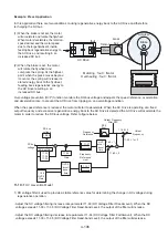
PID output polarity can be selected with parameter 10-03 (setting = 1: PID output forward, setting = 3: PID output
reversal). When PID output is set to “reverse”, and if PID input is negative, the output frequency of PID will increase.
When PID output is set to “forward”, and if PID input is still negative, the output frequency of PID will decrease.
PID feedback value can be adjusted using parameter 10-04 (PID feedback gain) or with the analog input gain and
bias for terminal AI1 or AI2.
Use the following procedures to enable PID control:
STEP 1
: Increase the proportional gain (10-05) to the highest value possible without causing the system to become
unstable.
STEP 2
: Decrease the integral time (10-06) to the lowest value possible without causing the system to become
unstable.
STEP 3
: Increase the differential time (10-07) to the highest value possible without causing the system to become
unstable.
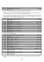
10-05
Proportional gain (P) Default: 1
Range
【
0.00–10.00
】
10-05 Proportional Gain control
: The error signal (deviation) between the input command (set value) and the actual
control value (feedback). This error signal or deviation is amplified by the proportional gain (P) to control the offset
between the set value and the feedback value.
10-06
Integral time (I) Default: 1
Range
【
0.0–100.0
】
Sec
10-06 Integral control
: The output of this control is the integral of the error signal (difference between set value and
feedback value) and is used to minimize the offset signal that is left over from the gain control. When the integral time
(I) is increased, the system response becomes slower.
10-04
Feedback gain Default: 1
Range
【
0.01–10.00
】
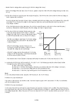
Feedback (detected value) is derivative controlled and set by parameter 10-07.
Make sure to adjust the PID parameters without causing system instability. Refer to Figure above for PID control for
feedback value differential.
For 10-03 = 0001b or 0010b, if error signal (target minus feedback) is positive, output frequency increases and vice versa.
For 10-03 = 0011b or 0100b, if error signal (target minus feedback) is positive, output frequency decreases and vice versa.
10-01
X
10-04
= Feedback Value