Fluke Biomedical IDA-4 Plus Operators Operator'S Manual Download Page 47


Infusion Pump Analyzer 


Operating Instructions 

3


3-25 

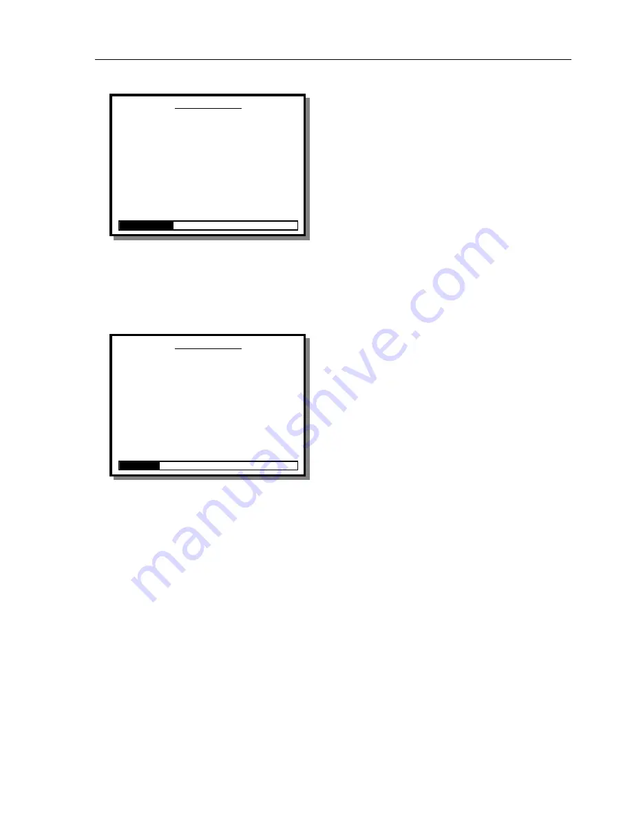
PCA Test Screen (Start Mode) 

When the measuring circuit is primed successfully the 
screen changes as shown. 

Auto-Start 

Pressing 

ENTER

 on this option puts the 

IDA-4 Plus


into 

AutoSTART

 mode. The prompt will flash until the 

instrument detects that the fluid is flowing, then start 
the test. 

Start 

When the measuring circuit is primed successfully the 
screen changes as shown. The following menu options 
are available: 

ESC 

Selecting 

ESC

 or pressing the 

ESC

 key on the external 

keyboard takes the operator back to the 

CHANNEL 

SETUP

 menu. 

PCA Test Screen (Measuring Mode) 

When the 

PCA TEST

 is started the screen enters 

measuring mode as shown. This enables further menu 
options.  

Status 

This takes the operator to the 

STATUS ALL 

CHANNELS

 screen. 

Graph 

This selection displays the 

PCA GRAPH

 screen to 

view the bolus delivery verses time graph. 

Bolus / Trig 

This triggers a PCA Bolus request to the pump if the 
pump can be triggered electrically. 

This requires the 

PCA Trigger / Remote Call Interface

If the pump 

does not have an electrical trigger (e.g. pneumatic) then 
this button may be pressed simultaneously with the 
patient button on the pump to allow the request for 
bolus to be recorded.  

End 

This ends the test and advance to the End of Test Mode. 

C h a n n e l     1     P C A  

L a s t     B o l u s  


A v e r a g e

0 . 0 0  

V o l u m e     m l  

0 . 0 0

0 . 0 0   F l o w  


R a t e  

0 . 0 0

          0 

D u r a t i o n  

              0 


I n t e r v a l  


B o l u s     C o u n t  

    0  

B a s a l     F l o w     R a t e  

        0 .   0 0     m l   / h  

E l a p s e d     T i m e  

0 0 :   0 0 :   0 0  

T o t a l     V o l u m e  

            0 .   0 0     m l  


AutoSTART 

START STATUS ESC

C h a n n e l     1     P C A  

L a s t     B o l u s  


A v e r a g e

0 . 0 0  

V o l u m e     m l  

0 . 0 0

0 . 0 0   F l o w  


R a t e  

0 . 0 0

          0 

D u r a t i o n  

              0 


I n t e r v a l  


B o l u s     C o u n t  

    0  

B a s a l     F l o w     R a t e  

        0 .   0 0     m l   / h  

E l a p s e d     T i m e  

0 0 :   0 0 :   0 0  

T o t a l     V o l u m e  

            0 .   0 0     m l  


STATUS 

GRAPH 

BOLUS / TRIG 

END

Summary of Contents for Biomedical IDA-4 Plus Operators

Page 1: ...IDA 4 Plus Infusion Pump Analyzer Operators Manual...

Page 2: ......

Page 3: ...IDA 4 Plus Infusion Pump Analyzer Operators Manual April 2005 2005 Fluke Corporation All rights reserved Printed in USA All product names are trademarks of their respective companies...

Page 4: ...IDA 4 Plus Operators Manual ii...

Page 5: ...anty and Product Support x Warranty Disclaimer x Introduction 1 1 Thank you 1 1 Introduction 1 1 Device Compatibility 1 1 About This Manual 1 1 Features 1 2 Package Contents 1 2 Specifications 1 3 Ele...

Page 6: ...Test Screen Start Mode 3 15 Flow Test Screen Measuring Mode 3 16 Flow Test Screen End of Test Mode 3 17 Flow Graph Screen 3 18 Occlusion Test Screen 3 19 Occlusion Test Screen Wait Mode 3 19 Occlusion...

Page 7: ...A 2 Gravity Controllers A 2 General A 2 Drip Rate Controllers A 3 Accuracy of Drip Controlled Devices A 3 Volumetric Controllers A 3 Infusion Pumps A 4 General A 4 Drip Rate Pumps A 4 Volumetric Pumps...

Page 8: ...IDA 4 Plus Operators Manual vi...

Page 9: ...is assumed by Fluke Biomedical for the use or reliability of software or equipment that is not supplied by Fluke Biomedical or its affiliated dealers Claims Our routine method of shipment is via comm...

Page 10: ...solvents or strong chemicals may also damage or contaminate the transducer Do not use Bleach type of sterilizing agents or alcohol s To extend the life of the transducer and to maintain accuracy it is...

Page 11: ...king Remove as much internal water as possible as described above Store away from sunlight Protect from frost internal water may freeze and expand Protect from vibration and shock The unit is a delica...

Page 12: ...state province to province or country to country This warranty is limited to repairing the instrument to Fluke Biomedical s specifications Warranty Disclaimer Should you elect to have your instrument...

Page 13: ...lity The purpose of this unit is to quickly establish the state of any given infusion device and to determine the performance qualities of the device This instrument can test and evaluate virtually an...

Page 14: ...easurement of Occlusion Pressure 9 Measurement of Back Pressure 9 Menu driven Utilities settings 9 LCD liquid crystal display super twist Graphics with back light Package Contents The contents of this...

Page 15: ...um sample sizes of 60 micro liters Range 0 06 9999 ml Accuracy 1 of reading 1 LSD for flows of 16 200 ml hr for volumes over 20 ml Otherwise 2 of reading 1LSD after delivery of 10 ml under laboratory...

Page 16: ...30 C up to 50 Relative Humidity Storage 0 40 C at 85 RH or less Do not leave for more than 48 hours at 20 C Transportability If possible use the packaging supplied by the manufacturer If this is not p...

Page 17: ...isplaying results on the LCD and can subsequently print saved test results via a printer port and or download saved test results to a PC via an RS232 port The unit may also be linked to controlled by...

Page 18: ...al Display 240 dot W x 128 H Graphic and Alphanumeric With backlight 2 Up Down Right and Left key pad switches 3 Enter keypad 4 Power ON Indicator 5 Channel 1 Fluid IN connector 6 Channel 2 Fluid IN c...

Page 19: ...Infusion Pump Analyzer An Overview 2 2 3 Front Panel Layout Drawing channel 1 channel 2 inlets channel 3 channel 4 1 2 3 4 5 6 7 8...

Page 20: ...rinter Port 25 way Female Configured in the same way as a PC Printer Port 14 Bar Code Wand Port 9 way Female Configured for HP Smart Wand 2400 Baud n 8 1 15 Computer RS232 Port 9 way Female Configured...

Page 21: ...Infusion Pump Analyzer An Overview 2 2 5 Rear Panel Layout Drawing...

Page 22: ...IDA 4 Plus Operators Manual 2 6...

Page 23: ...he drainage vessel and should not be joined in any way Note Infusion device measurement accuracy is also affected by the compliance of the infusion device and delivery tubes This is because there is a...

Page 24: ...IDA 4 Plus Operators Manual 3 2 Inlet Hose Connections Drawing...

Page 25: ...Infusion Pump Analyzer Operating Instructions 3 3 3 Outlet Hose Connections Drawing USE ONLY 250V FUSES DRAINAGE TUBES TO FLUID COLLECTION VESSEL...

Page 26: ...e date to your time zone The IDA 4 Plus contains a battery backed real time clock device to maintain time and date when the instrument is switched off This is used to time stamp the start of tests It...

Page 27: ...t Kent BR7 5PG United Kingdom Tel 0208 467 8944 Warning of Contamination Care should also be taken to prevent dirt dust metal swarf or other debris from entering the measuring system since these are l...

Page 28: ...Moving the cursor to UTIL and pressing ENTER invokes the UTILITIES menu Pressing the ENTER key with the cursor over SETUP invokes the CHANNEL SETUP menu for the appropriate channel The units of pressu...

Page 29: ...ng YES and pressing ENTER will DELETE ALL results Make sure you have printed or downloaded any records that you need Selecting NO returns to the UTILITIES menu Set Clock To Set the Clock use the left...

Page 30: ...is not inserted and form feeds are not sent This is suitable for most narrow paper strip printers Lines page This allows the number of printed lines per page to be adjusted 55 lines allow U S letter...

Page 31: ...ntinue until header is complete Moving the cursor to any OK position accepts the text and move to the next field or screen Selecting DEL deletes a character and the ESC character escapes back to the p...

Page 32: ...een mmHg kPa and psi use the up and down keys to change then press ENTER to accept The chosen units of pressure measurement are stored thereafter until changed via this screen and appear on all screen...

Page 33: ...results Flow This advances to the FLOW TEST screen where the operator will be guided through Flow tests It will not be possible to save the test results Dual Flow This advances to the DUAL FLOW INFORM...

Page 34: ...that uniquely identifies the infusion device being tested The cursor will be positioned in this field when the screen is first displayed When field is completed pressing ENTER advances to the Operator...

Page 35: ...field is optional and is used to record the manufacturer of the device under test This field has a maximum size of sixteen characters Pressing ENTER from this field advances to the Device Type field...

Page 36: ...orrect any of the preceding information that may have been entered incorrectly Flow This advances to the FLOW TEST screen where the operator will be guided through a flow rate test Occlusion This adva...

Page 37: ...eed to do this if you need to set up more than one channel ESC Selecting ESC or pressing the ESC key on the external keyboard will take the operator back to the CHANNEL SETUP menu Flow Test Screen Sta...

Page 38: ...START mode depending on the current state of the transducer The results of the subsequent test will be appended to those of the test terminated by this option Occlusion This ends the current test cle...

Page 39: ...printer connected to the printer port on the instrument The report will be in either full or summary format as previously selected by the operator from the UTILITIES PRINTER menu Graph This switches t...

Page 40: ...ime are displayed to the right of the graph Two dashed lines represent percentage deviation marks The percentage can be set from the TEST PARAMETERS SCREEN Status This switches to the STATUS ALL CHANN...

Page 41: ...r into a Tare measuring mode i e subtracts the ambient pressure While the transducer is in this mode the WAIT prompt is displayed Wait This menu option is never active it informs the operator to wait...

Page 42: ...Graph This switches to the OCCLUSION GRAPH screen for the current channel Flow This ends the current test clears the values from the screen and proceeds to the FLOW TEST screen in either PRIME or STA...

Page 43: ...ES PRINTER menu Print This sends a report to a printer connected to the printer port on the instrument The report will be in either full or summary format as previously selected by the operator from t...

Page 44: ...his will be the peak pressure reached and the time that the peak was reached The pressure units are those selected from the TEST PARAMETERS SCREEN Status This switches to the STATUS ALL CHANNELS scree...

Page 45: ...s recorded for information purposes only Pressing ENTER in this field advances the program to the Lockout Time minutes field Pressing ESC will step back to the Total Volume field Lockout Time minutes...

Page 46: ...e measured basal rate total delivered volume total test time and time interval between the last two boluses delivered PCA Test Screen Prime Mode When the screen is first displayed the operator is prom...

Page 47: ...he STATUS ALL CHANNELS screen Graph This selection displays the PCA GRAPH screen to view the bolus delivery verses time graph Bolus Trig This triggers a PCA Bolus request to the pump if the pump can b...

Page 48: ...e printer port on the instrument The report will be in either full or summary format as previously selected by the operator from the UTILITIES PRINTER menu Status This switches to the STATUS ALL CHANN...

Page 49: ...s facility via the PCA Trigger Remote Call Interface Automated Bolus Trigger With pumps that can be triggered electrically the bolus trigger signals are generated at one second intervals starting befo...

Page 50: ...nections to allow alarm conditions of pumps to be monitored It connects to the IDA 4 Plus via the 15 Way socket on the rear panel Trigger One trigger button is provided for each channel to trigger a P...

Page 51: ...lus For voltage output remote call connect the higher potential to the ring and the lower potential or ground to the tip For relay output remote call the polarity does not matter Refer to the pump man...

Page 52: ...s to the DUAL RATE TEST screen Pressing ESC will backtrack to the Secondary Rate field Primary Rate This is the flow rate of the first part of the infusion If a Flow Rate has been entered on the DEVIC...

Page 53: ...ESC on the external keyboard takes the operator back to the CHANNEL SETUP menu Dual Rate Test Screen Start Mode When the measuring circuit is primed successfully the screen advances to the Start Mode...

Page 54: ...s Status This invokes the STATUS ALL CHANNELS screen Graph This switches to the DUAL FLOW GRAPH screen for the current channel Flow This ends the current test clear the values from the screen and proc...

Page 55: ...inter connected to the printer port on the instrument The report will be in either full or summary format as previously selected by the operator from the UTILITIES PRINTER menu Status This switches to...

Page 56: ...d at that rate and the duration of the primary flow This is followed by the secondary flow rate and volume delivered at the secondary flow rate Status This switches to the STATUS ALL CHANNELS screen t...

Page 57: ...are not recommended The following test arrangement is suggested for performing flow rate tests under back pressure The pressure at the outlet must be returned to zero before performing an occlusion p...

Page 58: ...Apparatus for Back Pressure Testing Drawing channel 1 channel 2 inlets channel 3 channel 4 3 WAY TAP FROM OUTLET CONNECTOR PRESSURE METER GAUGE FLUID IN FROM INFUSION DEVICE 1 OR 2 LITER BOTTLE e g ME...

Page 59: ...or best performance the unit should be regularly used and may be left between test sessions with water inside Care of the Instrument Case Clean using a damp cloth with a mild detergent The molded fron...

Page 60: ...channel fitted Initiating an occlusion test on each channel in turn each Fluid inlet must be vented to atmosphere at the start of the test and then raise the pressure to 1 Bar on each channel fitted a...

Page 61: ...ich the desired flow rate is set in milliliters per hour The device calculates the conversion from drops per minute to milliliters per hour Infusion Pumps Infusion pumps are powered devices to provide...

Page 62: ...to those types mentioned above but they may have other advantages such as simplicity and the ability to operate in difficult environments Spring driven clockwork and gas powered infusion devices are...

Page 63: ...may not be The normal drops ml for a set or the value taken from a conversion chart are approximate and the actual drops ml may differ considerably The volume of fluid in a drop depends on a number of...

Page 64: ...softer tubing and special sets are provided with a pumping insert made of suitable material Pumps that use drop sensing as their means of control do not normally compensate for variation in drop size...

Page 65: ...a volumetric pump and the resultant short term fluctuations are of much smaller magnitude There have been problems with backlash slackness which causes start up and alarm delays in the pump overcome b...

Page 66: ...erapy pain relief and other applications where very small volumes are to be infused over periods of days rather than hours and where the patient is at home rather than in a hospital ward They can typi...

Page 67: ...software enabled by programming or smart card for example in a pump that is otherwise suitable for other applications they must be disabled before these pumps are used in any other application Manage...

Page 68: ...IDA 4 Plus Operators Manual A 8...

Page 69: ...the type of test in progress Controlling the IDA 4 Plus with HydroGraph The IDA 4 Plus can be operated using a computer running HydroGraph software Follow the steps below to get started Power off the...

Page 70: ...a command to end a communication session type BYE All commands instructing to perform a test needs to have a channel number attached to the command Some commands require more information in addition t...

Page 71: ...cclusion pressure test on the specified channel The IDA 4 Plus status all channels screen will prompt the operator to start the test The operator can either press the start key on the front panel or s...

Page 72: ...t b technician name c set primary flow rate d set primary volume e set secondary flow rate f set secondary volume Fetch the Current Flow Measured on a Channel FLOWn Returned to host Flow nnnn nn hh mm...

Page 73: ...e in the selected units hh mm ss mmm is the time since the start of the test formatted as hh Hours mmMinutes ss Seconds mmm Milli seconds Fetch the Peak Pressure on a Channel PKPRESn Returned to host...

Page 74: ...Starts an Occlusion Test 3 n Channel number CnPCA a b c Starts a PCA test 3 n Channel number CnD a b c d e f Starts a Dual Flow Test 6 n Channel number END n End a Test n Channel number FLOWn Fetches...

Reviews: