


9100A-017
7-7
MC6845 CRT CONTROLLER BUS CYCLES
7.7.
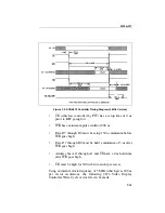
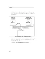
Examine the timing diagram for the MC6845 (shown in Figure
7-1) to determine the vector patterns necessary to achieve the
required bus cycles.
To perform a read/write cycle, the following conditions must be
met:
•
The address (RS) and read/write (R/W) signal must be set a
minimum of 80 ns before the rising edge of the E clock and
held for 10 ns after the falling edge of the clock.
•
WRITE DATA must be set a minimum of 165 ns before the
falling edge of the E clock and held for 10 ns after the fall-
ing edge of the clock.
•
READ DATA must be output a maximum of 290 ns after
the rising edge of the E clock and will be held for a maxi-
mum of 50 ns after the falling edge of the E clock.
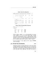
Figure 7-1. MC6845 Cycle Timing Diagram
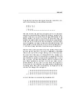
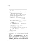
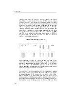
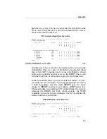
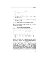
The following CRT Controller Write Cycle Vector File contains
the vectors necessary to perform the write cycle. Since the
driven vectors are synchronized with the 6 MHz bus clock, each
Summary of Contents for 9100A Series
Page 6: ...vi ...
Page 8: ...viii ...
Page 10: ...x ...
Page 14: ...9100A 017 1 4 ...
Page 24: ...9100A 017 3 6 ...
Page 44: ...9100A 017 5 4 ...
Page 58: ...9100A 017 6 14 ...
Page 83: ...A 1 Appendix A New TL 1 Commands ...
Page 84: ...9100A 017 A 2 ...
Page 87: ...clockfreq 3 For More Information The Overview Of TL 1 section of the Programmer s Manual ...
Page 88: ...clockfreq 4 ...
Page 91: ...drivepoll 3 For More Information The Overview Of TL 1 section of the Programmer s Manual ...
Page 92: ...drivepoll 4 ...
Page 104: ...vectordrive 4 ...
Page 107: ...vectorload 3 For More Information The Overview Of TL 1 section of the Programmer s Manual ...
Page 108: ...vectorload 4 ...
Page 116: ...9100A 017 C 2 ...
Page 117: ...9100A 017 C 3 ...
Page 118: ...9100A 017 C 4 ...


