6-1
Section 6
Using the Vector Editor
INTRODUCTION
6.1.
To be able to drive vectors out the 9100A-017 Vector Output I/O
Module, a vector file must be created. This file contains all the
information required by the module to output the proper se-
quence of signals. When used in conjunction with the various
signal inputs and outputs of the Vector Output I/O Module, con-
trol of the vector patterns and handshaking between the module
and the UUT is greatly enhanced.
To use the Vector Editor, you must be familiar with the basic
operations of the 9100A Editor. Operation of the 9100A Editor
is covered in the
9100 Series Programmer’s Manual
.
CREATING A NEW VECTOR FILE
6.2.
To create a new vector file, press the EDIT key, enter the path
name (for example, “/hdr/tmp/vec1”) followed by <CR>, and
press the FIELD SELECT key until VECTOR is displayed in the
TYPE field. Press <CR>. When the file is created, the follow-
ing text is displayed:
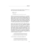
GROUPS [40-1]
DISPLAY BIN
!TIME DATA
1
Summary of Contents for 9100A Series
Page 6: ...vi ...
Page 8: ...viii ...
Page 10: ...x ...
Page 14: ...9100A 017 1 4 ...
Page 24: ...9100A 017 3 6 ...
Page 44: ...9100A 017 5 4 ...
Page 58: ...9100A 017 6 14 ...
Page 83: ...A 1 Appendix A New TL 1 Commands ...
Page 84: ...9100A 017 A 2 ...
Page 87: ...clockfreq 3 For More Information The Overview Of TL 1 section of the Programmer s Manual ...
Page 88: ...clockfreq 4 ...
Page 91: ...drivepoll 3 For More Information The Overview Of TL 1 section of the Programmer s Manual ...
Page 92: ...drivepoll 4 ...
Page 104: ...vectordrive 4 ...
Page 107: ...vectorload 3 For More Information The Overview Of TL 1 section of the Programmer s Manual ...
Page 108: ...vectorload 4 ...
Page 116: ...9100A 017 C 2 ...
Page 117: ...9100A 017 C 3 ...
Page 118: ...9100A 017 C 4 ...


