


9100A-017
6-4
WORKING WITH THE VECTOR FILE
6.4.
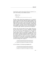
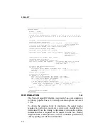
When a vector file is first created, four lines of text are automati-
cally created at the beginning of the file. These four line are:
GROUPS [40-1]
DISPLAY BIN
!TIME DATA
1
The first line is called the groups line. The second line is called
the display line. The third line is a comment line. The fourth line
is the beginning of the data fields. The following paragraphs
describe these lines in detail.
Blank lines are only allowed after the display line. If, during
editing, a blank line is inserted between the groups line and the
display line, an error message is displayed.
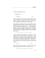
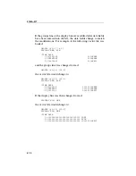
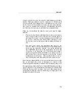
The Groups Line
6.5.
The first line of the display is the groups line. The groups line
determines how the pins of the Vector Output I/O Module are to
be grouped together. All 40 pins on the module must be listed in
this group. This line may be changed to group together the 40
pins using the following syntax:
GROUPS <label>[<group>]...
where GROUPS is the name of the line, <label> is an optional
label made of any ASCII characters except “[“, and <group> is
any number or range of numbers from 1 to 40 (in any order)
separated by a comma (,), a space ( ), or a comma and a space
(, )( ,). If more than 2 numbers are listed in a row, the numbers
can be shown using the beginning and ending number separated
by a dash (-). For example, pins 1, 2, 3, and 4 on the module can
be listed as 1-4.
More than one <label> and <group> pair can be listed on the
group line. For example, if you wanted to group together pins 1
Summary of Contents for 9100A Series
Page 6: ...vi ...
Page 8: ...viii ...
Page 10: ...x ...
Page 14: ...9100A 017 1 4 ...
Page 24: ...9100A 017 3 6 ...
Page 44: ...9100A 017 5 4 ...
Page 58: ...9100A 017 6 14 ...
Page 83: ...A 1 Appendix A New TL 1 Commands ...
Page 84: ...9100A 017 A 2 ...
Page 87: ...clockfreq 3 For More Information The Overview Of TL 1 section of the Programmer s Manual ...
Page 88: ...clockfreq 4 ...
Page 91: ...drivepoll 3 For More Information The Overview Of TL 1 section of the Programmer s Manual ...
Page 92: ...drivepoll 4 ...
Page 104: ...vectordrive 4 ...
Page 107: ...vectorload 3 For More Information The Overview Of TL 1 section of the Programmer s Manual ...
Page 108: ...vectorload 4 ...
Page 116: ...9100A 017 C 2 ...
Page 117: ...9100A 017 C 3 ...
Page 118: ...9100A 017 C 4 ...


