9100A-017
7-6
Fixturing Considerations
7.5.
Fixturing between the Vector Output I/O Module and the CGA
Card is minimal. To keep line lengths as short as possible and to
keep interfacing easy, the Y9100A-102 Card Edge Interface
Module is recommended. Most lines from the card edge module
to the CGA card-edge connector match except for the following:
•
IOCLK
To provide the 6 MHz bus timing clock, a 24 Mhz
Oscillator is divided by four using a 74LS74 D Flip-Flop
(that is placed on the Performance board in the Card Edge
Fixture Kit). The clock is connected to pin B20 of the CGA
connector, and to pin 6 and DR CLK (to synchronize the
vectors with the bus) on the Vector Output I/O Module.
•
IORDY
The IORDY line is connected to pin A10 of the CGA
connector, and pin 8 and WAIT (to provide Video RAM
synchronization) of the Vector Output I/O Module. A
pullup resistor is added to this line on the performance
board of the Card Edge Fixture Kit.
•
14 MHz
An external signal generator provides the 14.31818 MHz
signal required for Video Sync.
•
+5V, +12V, GND
An external power supply provides the required voltages to
a DPDT switch that controls the power to the CGA Card.
Vector File Programming
7.6.
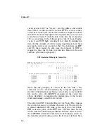
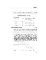
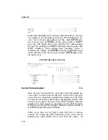
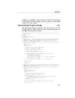
To control the CGA card, the proper vector patterns to perform
read and write bus cycles must be determined and placed in
vector files. There are two sets of these cycles on the CGA card:
one set to communicate with the MC6845 CRT Controller and
another to access the video RAM.
Summary of Contents for 9100A Series
Page 6: ...vi ...
Page 8: ...viii ...
Page 10: ...x ...
Page 14: ...9100A 017 1 4 ...
Page 24: ...9100A 017 3 6 ...
Page 44: ...9100A 017 5 4 ...
Page 58: ...9100A 017 6 14 ...
Page 83: ...A 1 Appendix A New TL 1 Commands ...
Page 84: ...9100A 017 A 2 ...
Page 87: ...clockfreq 3 For More Information The Overview Of TL 1 section of the Programmer s Manual ...
Page 88: ...clockfreq 4 ...
Page 91: ...drivepoll 3 For More Information The Overview Of TL 1 section of the Programmer s Manual ...
Page 92: ...drivepoll 4 ...
Page 104: ...vectordrive 4 ...
Page 107: ...vectorload 3 For More Information The Overview Of TL 1 section of the Programmer s Manual ...
Page 108: ...vectorload 4 ...
Page 116: ...9100A 017 C 2 ...
Page 117: ...9100A 017 C 3 ...
Page 118: ...9100A 017 C 4 ...

