


9100A-017
6-5
through 4 and pin 6, and put the rest of the pins in another group,
the groups line would be changed to read:
GROUPS [1-4,6][5,7-40]
Note that the groups line in the previous example did not use the
optional <label>. If, however, you want to add a label that
designates pins 1 through 4 and 6 as control lines, the groups
line could be changed to read:
GROUPS control[1-4,6][5,7-40]
If the second group consists of address lines, the groups line
could be changed to read:
GROUPS control[1-4,6]address[5,7-40]
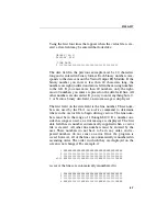
Any combination of numbers from 1 to 40 in any order can be
listed on the <group>. A <group> consists of a minimum of
one number (i.e., [24]) and a maximum of forty numbers (i.e.,
[40-1]). All forty pins of the Vector Output I/O Module must be
listed. For example, if all the <group>s consisted of one num-
ber, forty <group>s would be listed on the groups line.
The Display Line
6.6.
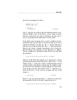
The display line specifies whether the data shown in the data
fields are displayed in binary or hexadecimal. When a vector file
is first created, the display line is shown as:
DISPLAY BIN
This designates that all forty pins in the data field are displayed
in binary. If you want all the pins in the data fields to be dis-
played in hexadecimal, change the display line to read:
DISPLAY HEX
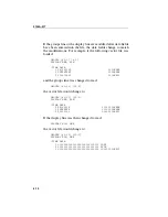
If more than one group exists in the groups line, each of the
groups can be displayed individually as either binary or
hexadecimal. A comma or a comma and a space is used to
separate the designators. For instance, if there are two groups
Summary of Contents for 9100A Series
Page 6: ...vi ...
Page 8: ...viii ...
Page 10: ...x ...
Page 14: ...9100A 017 1 4 ...
Page 24: ...9100A 017 3 6 ...
Page 44: ...9100A 017 5 4 ...
Page 58: ...9100A 017 6 14 ...
Page 83: ...A 1 Appendix A New TL 1 Commands ...
Page 84: ...9100A 017 A 2 ...
Page 87: ...clockfreq 3 For More Information The Overview Of TL 1 section of the Programmer s Manual ...
Page 88: ...clockfreq 4 ...
Page 91: ...drivepoll 3 For More Information The Overview Of TL 1 section of the Programmer s Manual ...
Page 92: ...drivepoll 4 ...
Page 104: ...vectordrive 4 ...
Page 107: ...vectorload 3 For More Information The Overview Of TL 1 section of the Programmer s Manual ...
Page 108: ...vectorload 4 ...
Page 116: ...9100A 017 C 2 ...
Page 117: ...9100A 017 C 3 ...
Page 118: ...9100A 017 C 4 ...


