9100A-017
6-7
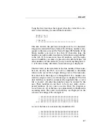
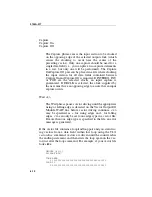
Using the first four lines that appear when the vector file is cre-
ated, a data field may be entered that looks like:
GROUPS [40-1]
DISPLAY BIN
!TIME DATA
1 1000000010001000100000000001111111110111
The data field in the previous example must be 40 characters
long and is entered in binary format. Each binary number corre-
sponds to the data sent out the Vector Output I/O Module. If the
binary number you enter is less than 40 characters long, the
numbers are right justified and zeroes fill in the missing numbers
to the left. If you enter more than 40 numbers, only the right-
most 40 numbers you enter are placed on the data field line. All
other numbers are discarded. If you try to enter anything but a 0,
1, or X into a binary data field, an error message is displayed.
The first field on the data field is the line number. These num-
bers are used by the TL/1
vectordrive
command to determine
where in the vector file to begin driving vectors. The line num-
bers must be in the range of 1 through 8192. If a number out-
side this range is used, an error message is displayed. The first
data field has its number automatically supplied when a vector
file is created. All other line numbers must be entered by the
user. These numbers do not have to be in any order, and re-
peated numbers do not cause an error. Once the program is
saved, however, all of the lines are automatically renumbered in
ascending order. The order in which they are displayed on the
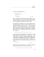
screen is not changed. For example, if:
2 XXXXXXXXXXXXXXXXXXXXXXXXXXXXXXXXXXXXXXXX
2 1111111111111111111111111111111111111111
1 0000000000000000000000000000000000000000
8000 XXXX00001111XXXX00001111XXXX00001111XXXX
is saved, the lines are automatically renumbered to:
1 XXXXXXXXXXXXXXXXXXXXXXXXXXXXXXXXXXXXXXXX
2 1111111111111111111111111111111111111111
3 0000000000000000000000000000000000000000
4 XXXX00001111XXXX00001111XXXX00001111XXXX
Summary of Contents for 9100A Series
Page 6: ...vi ...
Page 8: ...viii ...
Page 10: ...x ...
Page 14: ...9100A 017 1 4 ...
Page 24: ...9100A 017 3 6 ...
Page 44: ...9100A 017 5 4 ...
Page 58: ...9100A 017 6 14 ...
Page 83: ...A 1 Appendix A New TL 1 Commands ...
Page 84: ...9100A 017 A 2 ...
Page 87: ...clockfreq 3 For More Information The Overview Of TL 1 section of the Programmer s Manual ...
Page 88: ...clockfreq 4 ...
Page 91: ...drivepoll 3 For More Information The Overview Of TL 1 section of the Programmer s Manual ...
Page 92: ...drivepoll 4 ...
Page 104: ...vectordrive 4 ...
Page 107: ...vectorload 3 For More Information The Overview Of TL 1 section of the Programmer s Manual ...
Page 108: ...vectorload 4 ...
Page 116: ...9100A 017 C 2 ...
Page 117: ...9100A 017 C 3 ...
Page 118: ...9100A 017 C 4 ...


