


Theory of Operation (2620A/2625A)
Detailed Circuit Description
2
2-23
OHMS
VOLTAGE
SOURCE
A/D
INTEGRATE
REFERENCE
LOW
HIGH
A3R34
A3Z4
REFERENCE
RESISTOR
R
REF
+
–
VR
REF
A3K16
A3RT1 & A3R10
A3K17
UNKNOWN
RESISTOR
PASSIVE
FILTER
A/D
INTEGRATE
UNKNOWN
HIGH
LOW
I
X
A3R11
R
X
VR
X
VR
X
VR
REF
=
I
X
•R
X
I
X
•R
REF
R
REF
R
X
=
+
-
LO
HI
A3R42
s5f.eps
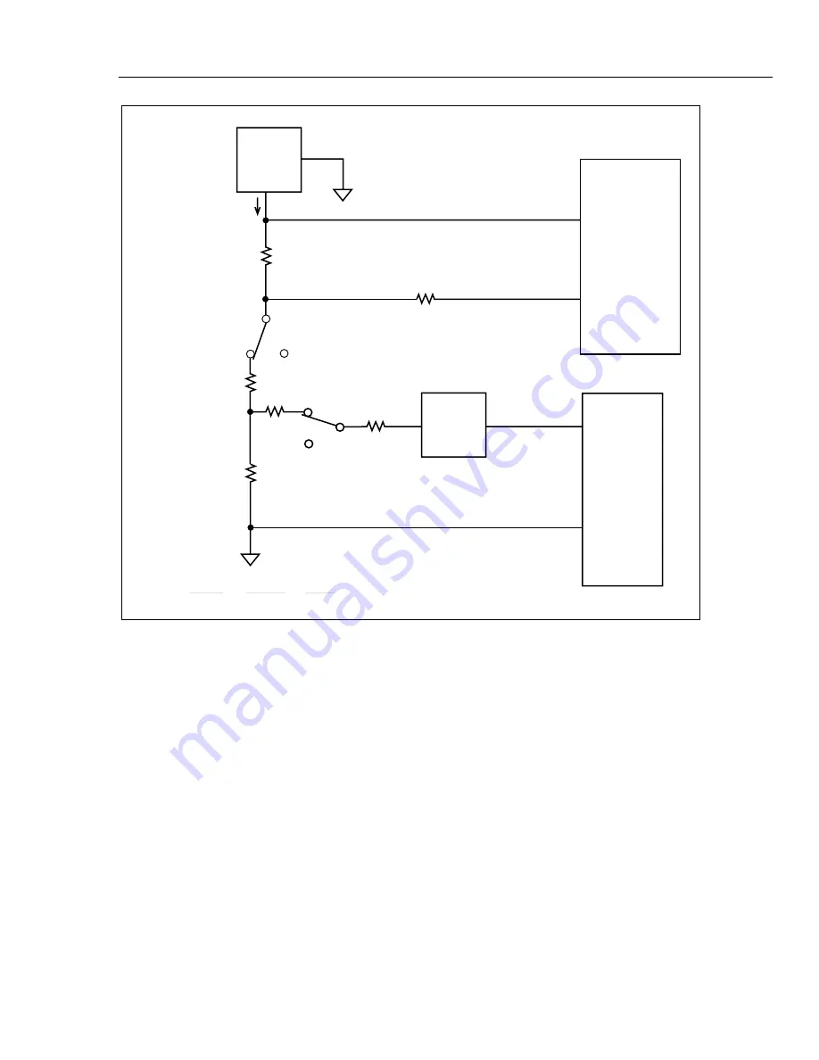
Figure 2-5. Ohms Simplified Schematic
The reference resistor for the 300-k
Ω
, 3-M
Ω
, and 10-M
Ω
ranges is the 1-M
Ω
resistor in
A3Z4, which is selected by S15. The voltage across this reference is integrated during its
own minor cycle(s) and is switched to a passive filter and the A/D Converter by switches
S1 and S18.
When 4-wire measurements are made on any of the six ranges, separate Source and
Sense signal paths are maintained to the point of the unknown resistance. The 4-wire
Source path measurement current is provided by the A3U8 ohms source through one of
the A3U8 internal switches (S6, S9, S13, or S15) and the appropriate reference resistor
in A3Z4. The current flows through relay A3K16, thermistor A3RT1, resistor A3R10,
the HI Source instrument relay contacts (A3K1 - A3K3, A3K5 - A3K14), and the HI
Source lead wire, to the unknown resistance to be measured. The current flows back
through the LO Source lead wire, the LO Source path of the instrument relays (A3K1 -
A3K3, A3K5 - A3K14), resistor A3R43, and analog ground, to the A3U8 ohms source.
The voltage that develops across the unknown resistance is sensed through the other 2
wires of the 4-wire set. HI is sensed through the HI Sense path made up of the users HI
Sense lead wire, the HI Sense contacts in the instrument relays, resistor A3R11, relay
A3K17, resistor A3R42, and Analog Processor A3U8 switch S2. LO is sensed through
the users LO Sense lead wire, the LO Sense contacts in the instrument relays, protection
resistor A3R35, and A3U8 switch S19.
Summary of Contents for 2620A
Page 4: ......
Page 18: ...HYDRA Service Manual 1 2...
Page 48: ...HYDRA Service Manual 1 32...
Page 140: ...HYDRA Service Manual 3 16...
Page 234: ...HYDRA Service Manual 5A 34...
Page 236: ...HYDRA Service Manual 6 2...
Page 254: ...HYDRA Service Manual 6 20 2620A 1601 s63f eps Figure 6 3 2620A 2625A A1 Main PCA...
Page 258: ...HYDRA Service Manual 6 24 2635A 1601 s64f eps Figure 6 4 2635A A1 Main PCA...
Page 260: ...HYDRA Service Manual 6 26 2620A 4002 CKT 1 CKT 2 s65f eps Figure 6 5 A2 Display PCA...
Page 272: ...HYDRA Service Manual 6 38...
Page 274: ...HYDRA Service Manual 7 2...
Page 282: ...HYDRA Service Manual 7 10...
Page 284: ...HYDRA Service Manual 8 2...
Page 285: ...Schematic Diagrams 8 8 3 Figure 8 1 A1 Main PCA 2620A 2625A 2620A 1601 s88f eps...
Page 288: ...Schematic Diagrams 8 8 6 Figure 8 1 A1 Main PCA 2620A 2625A cont 2620A 1001 3 of 4 s73f eps...
Page 292: ...Schematic Diagrams 8 8 10 2635A 1001 2 of 5 Figure 8 2 A1 Main PCA 2635A cont s76f eps...
Page 293: ...Schematic Diagrams 8 8 11 2635A 1001 3 of 5 Figure 8 2 A1 Main PCA 2635A cont s77f eps...
Page 296: ...Schematic Diagrams 8 8 14 2620A 4002 CKT 1 CKT 2 Figure 8 3 A2 Display PCA s90f eps...
Page 300: ...Schematic Diagrams 8 8 18 2620A 1003 2 of 3 Figure 8 4 A3 A D Converter PCA cont s82c eps...
Page 301: ...Schematic Diagrams 8 8 19 2620A 1003 3 of 3 Figure 8 4 A3 A D Converter PCA cont s83c eps...
Page 302: ...Schematic Diagrams 8 8 20 2620A 1604 Figure 8 5 A4 Analog Input PCA s92f eps...
Page 304: ...Schematic Diagrams 8 8 22 2620A 1605 Figure 8 6 A5 IEEE 488 Interface PCA 2620A Only s93f eps...
Page 306: ...Schematic Diagrams 8 8 24 2625A 1606 Figure 8 7 A6 Memory PCA 2625A s94f eps...
Page 310: ...Schematic Diagrams 8 8 28...


