FLUXUS ADM 8027, F801, ADM 8127B
A Menu Structure
138
UMFLUXUS_F8V4-6-1EN, 2018-10-10
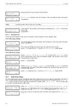
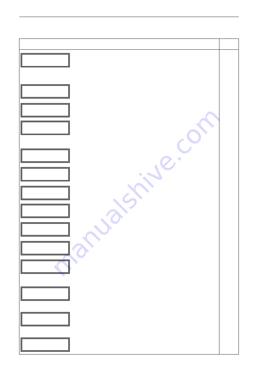
input of the error value delay, i.e. the time interval after which the error value
is transmitted to the output in case no valid measured values are available
This display will only be indicated if
Special Funct.\SYSTEM set-
tings\Dialogs/Menus\Error-val. delay
=
EDIT
is selected.
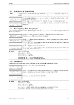
Pulse output
activation of a Pulse Output
This display will only be indicated if a pulse output has been installed in
SYS-
TEM settings
\
Proc. outputs
\\.
input of the pulse value (totalizer value at which a pulse will be emitted)
This display will only be indicated if
Pulse Output
is activated.
input of the pulse width
range: 1...1000 ms
This display will only be indicated if
Pulse Output
is activated.
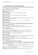
Alarm output
Activation of an Alarm Output
This display will only be indicated if an alarm output has been installed in
Special Funct.\SYSTEM settings\Proc. outputs
.
Selection of the switching condition (
func
), the holding behavior (
typ
) and
the switching function (
mode
) of the alarm output.
This display will only be indicated if
Alarm Output
is activated.
selection of the physical quantity to be monitored
This display will only be indicated for R1 if
Alarm Output
is activated.
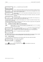
input of the upper limit of the physical quantity to be monitored
This display will only be indicated if
Alarm Output
is activated and
MAX
is
selected as the switching condition.
input of the lower limit of the physical quantity to be monitored
This display will only be indicated if
Alarm Output
is activated and
MIN
is
selected as the switching condition.
input of the limit for the flow totalizer of the physical quantity to be monitored
This display will only be indicated if
Alarm Output
is activated and
QUANT.
is selected as the switching condition.
input of the hysteresis for the lower or upper limit
This display will only be indicated if
Alarm Output
is activated and
MIN
or
MAX
is selected as the switching condition.
Program branch
Special Funct.
main menu: selection of the program branch
Special Funct.
SYSTEM settings
selection of
Special Funct.\SYSTEM settings
SYSTEM settings\Set Clock
selection of the displays for the input of the date and the time
INIT-resis-
tant
Error-val. delay
10
s
Pulse Output
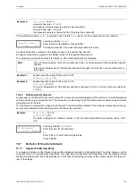
B1: no
>YES<
Pulse Value
0.01
m3
Pulse Width
100
ms
Alarm Output
no
>YES<
R1=FUNC<typ mode
Function:
MAX
R1 Input:
↕
Volume flow
High Limit:
-10.00
m3/h
Low Limit:
-10.00
m3/h
Quantity Limit:
1.00
m3
R1 Hysterese:
1.00
m3/h
par mea opt >SF<
Special Funct.
Special Funct.
↕
SYSTEM settings
SYSTEM settings
↕
Set Clock

