


FLUXUS ADM 8027, F801, ADM 8127B
9 Mounting of the Transducers
70
UMFLUXUS_F8V4-6-1EN, 2018-10-10
9.4.3
Installation of the Transducers in Variofix C
• Put coupling foil (or some coupling compound for a short-term installation) on the contact surface of the transducers. The
coupling foil can be fixed to the contact surface with a small amount of the coupling compound.
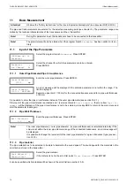
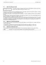
• Position the transducers on the rail in such way that the engravings on the transducers form an arrow. The transducer
cables show in opposite directions (see Fig. 9.45).
• Adjust the transducer distance displayed by the transmitter (see section 11.6 and Fig. 9.45).
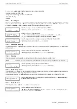
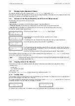
• Slide the spring clips on the transducers (see Fig. 9.46).
• Fix the transducers by tightening the tensioning screws slightly. The end of the screw has to be placed above the hole in
the transducer (see Fig. 9.45).
• Correct the transducer distance, if necessary (see section 11.6.1 and section 11.6.2).
• Tighten the tensioning screw.
• Fix the spacing element on the rail to mark the transducer position (see Fig. 9.45).
• Use a cable tie to fix the transducer cables in order to protect them from mechanical strain (see Fig. 9.46).
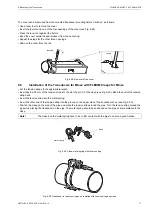
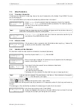
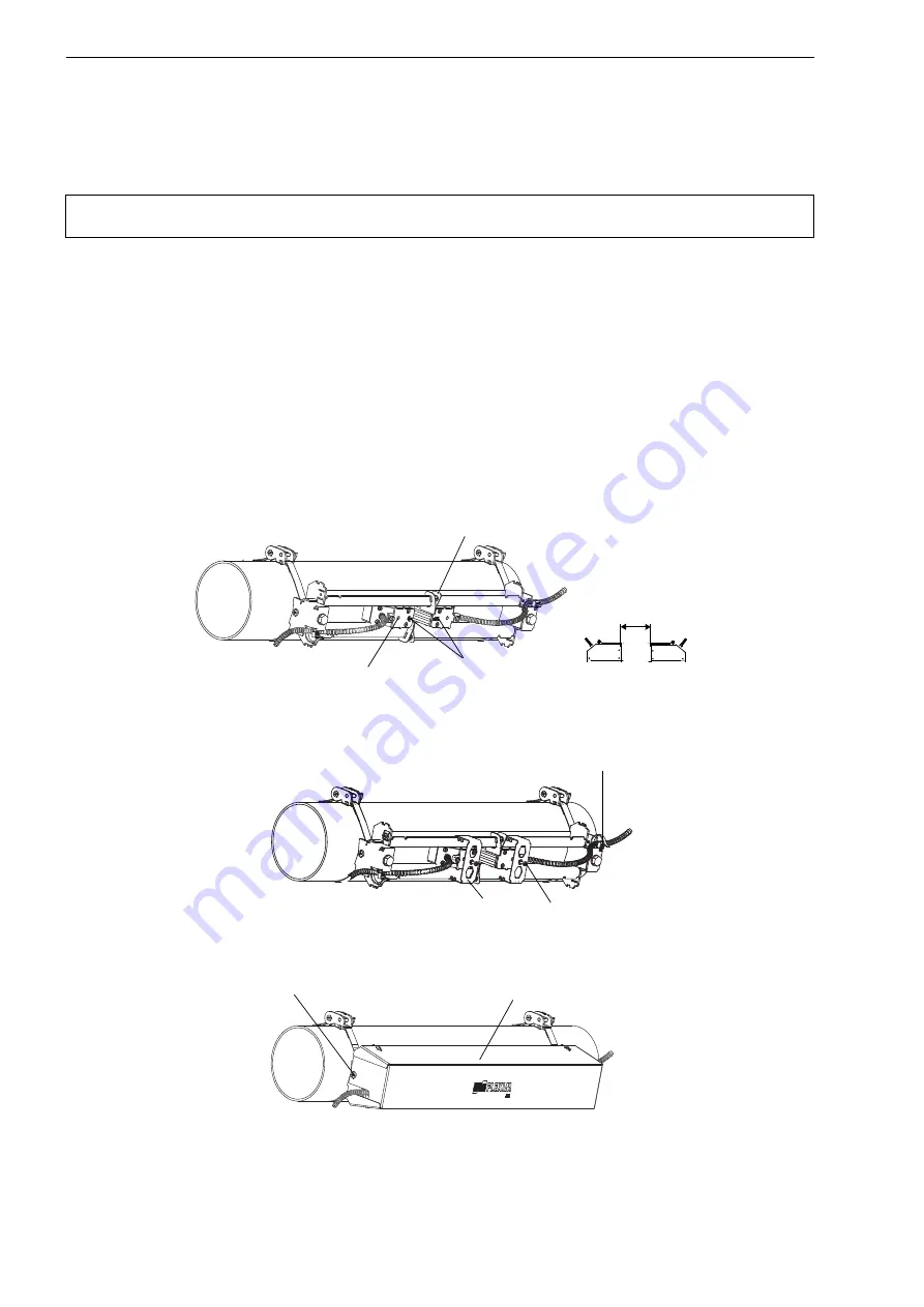
• Put the cover on the rail (see Fig. 9.47).
• Tighten the screws on both sides of the cover.
Note!
If coupling foil is used: If the signal is not sufficient for the measurement, use the coupling compound
instead of the coupling foil.
Fig. 9.45: Transducers in the rail (spring clip not shown)
Fig. 9.46: Transducers in the rail
Fig. 9.47: Variofix C with transducer on the pipe
engravings on
the transducers
hole
spacing element
transducer distance
cable tie
tensioning screw
spring clip
cover
screw


