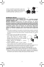
ASSEMBLING THE NEBULISER
Follow the assembly instructions below.
2. Place the valve (C1.1b) with the flat side down onto the particle size regulator
(C1.1a) by aligning the hole with the position ribs, then screw the selector (C1.1c)
onto the threaded pin of the regulator all the way down. Rotate the assembled
regulator to make sure that it turns freely and that the selector moves up and
down between positions.
C1.3
C1.2
C1.2
C1.3
4. Insert the assembled upper part
(C1.1 + C1.2 + C.13) into the lower part
(C1.4) and hook it by turning it clock-
wise.
C1.2
C1.1
C1.1c
a
b
C1.1+C1.2+C1.3
C1.4
1. Assemble the nozzle (C1.3) on the upper part (C1.2).
C1.3
C1.2
C1.2
C1.3
3. Insert and press the previously as-
sembled particle size regulator (C1.1) all
the way down, keeping it in a horizontal
position, in the upper part (C1.2), and
matching the partitions of the selector
(C1.1c) with the groove in the upper
part (C1.2).
C1.1a
C1.1b
C1.1c
C1.1a +
C1.1b
2
3
Summary of Contents for 4Neb
Page 2: ......
Page 44: ...FLAEM FLAEM 400 a b 93 42 E 2 42...
Page 47: ...C1 1 C1 2 1 A7 A8 2 C1 4 C1 1 C1 2 C1 3 C1 4 C1 2 C1 2 3 4 RF9 5 6 1 7 3 1 2 1 C1 1 C1 2 45...
Page 50: ...E FLAEM 48...
Page 65: ...400 CE 42 93 63...
Page 66: ...A6 1 2 C1 1 C1 2 C1 3 C1 4 C1 4 C1 2 C1 2 3 4 RF9 5 A1 6 7 B C1 1 C1 2 C1 1 C1 2 64...
Page 70: ...68...
Page 74: ...FLAEM FLAEM 400 a b 93 42 CE 2 72...
Page 77: ...C1 1 C1 2 C1 1 C1 2 1 A7 2 C1 4 C1 1 C1 2 C1 3 C1 4 C1 2 3 4 RF9 5 6 A1 7 B 3 1 ma 75...
Page 79: ...C C1 1 C1 1a C1 1b C1 1c C1 2 C1 3 C1 4 C2 C3 C4 6 A3 FLAEM...
Page 82: ...MEMO 80...
Page 83: ...81...

