


321144
95
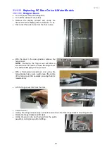
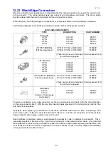
12.22 Flapper Element Replacement
1. Disconnect the refrigerator from the power supply.
2. Open the left hand PC door to expose the flapper.
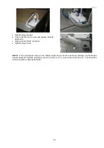
3. Remove the flapper spring. Refer Photo 12.22.1.
a. Using a pair of long nose pliers, remove the top part of the spring from flapper.
b. Once removed, the spring can be left in position.
4. Remove the bottom end cap off the flapper. Refer Photo 12.22.2
Locking clips are to be pushed in to remove cap.
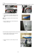
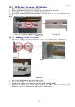
5. Remove the top screws holding the top flapper hinge to the door liner. Refer Photo 12.22.3
Second screw located in front of hinge.
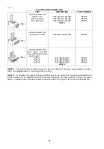
6. Remove the flapper off the bottom hinge and turn over to expose the bottom of the flapper.
7. Slide the element forward. Note: The element is taped onto the steel insert and may offer some
resistance. Care should be taken not to damage the insert or the product. Refer Photo 12.22.4
Pull element enough to expose JST connector.
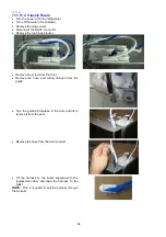
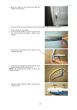
8. Disconnect the JST connector and remove the entire element.
9. Replacement and re-fitment of the element is in reverse order.
Cautionary NOTE:
Ensure the element
wiring is routed and/or is not under tension as it may cause early failure of the element. Refer Photo
12.22.5
Summary of Contents for 635 Active Smart
Page 1: ...321144 Service Manual 635 680 790 900 Active Smart Refrigerator Freezer R134a R600a Systems...
Page 2: ...321144 2...
Page 96: ...321144 96 Photo 12 22 5...
Page 100: ...321144 100 Diagram 12 25...
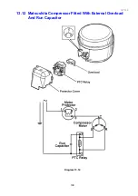
Page 108: ...321144 108 13 11 Embraco Compressor Fitted With External Overload Diagram 13 11...
Page 114: ...321144 114 14 2 Non Ice Water Models Wiring Diagram...
Page 116: ...321144 116 14 4 Ice Water Models Wiring Diagram...
Page 117: ...321144 117 14 5 900 Models Power Control Module Wiring Connections Reciprocating Compressor...
Page 118: ...321144 118 14 6 900 Models Wiring Diagram Reciprocating Compressor...
Page 119: ...321144 119 14 7 900 Models Power Control Module Wiring Connections VC Compressor...
Page 120: ...321144 120 14 8 900 Models Wiring Diagram VC Compressor...
Page 121: ...321144 121 14 9 B Model Wiring Route Diagram 14 9...
Page 122: ...321144 122 14 10 T Model Wiring Route Diagram 14 10...
Page 145: ......


