


321144
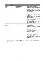
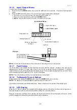
56
9.5
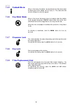
Changing The Water Filter
•
Turn water off. It is also recommended that the pressure is released by dispensing water with the
tap off.
•
Grasp and firmly twist the cartridge in an anticlockwise direction (to the left when installed in the
recommended orientation).
•
Pull the cartridge away from the filter head (down when installed in the recommended orientation).
•
Discard the old filter.
•
Remove the protective cap on the spigot on the head of the new cartridge.
•
Push the cartridge upwards towards the head while rotating it in a clockwise direction (to the right
when installed in the recommended orientation).
•
Reset the filter icon on the display (this will be set to remind the customer the filter is due to be
replaced).
Diagram 9.5
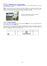
9.6
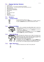
To Reset The Filter Icon
•
Press the
UP
and
LOCK
buttons for 4 seconds to reset the filter monitor.
Note:
Do not reset the monitor before the filter is changed, or monitoring will be inaccurate.
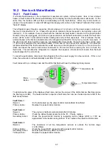
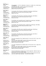
9.7
To Disable The Filter Alarm
Disable the alarm if no filter is to be fitted.
•
Press and hold the
MENU
,
UP
and
LOCK
buttons for 4 seconds to turn this feature on/off.
Summary of Contents for 635 Active Smart
Page 1: ...321144 Service Manual 635 680 790 900 Active Smart Refrigerator Freezer R134a R600a Systems...
Page 2: ...321144 2...
Page 96: ...321144 96 Photo 12 22 5...
Page 100: ...321144 100 Diagram 12 25...
Page 108: ...321144 108 13 11 Embraco Compressor Fitted With External Overload Diagram 13 11...
Page 114: ...321144 114 14 2 Non Ice Water Models Wiring Diagram...
Page 116: ...321144 116 14 4 Ice Water Models Wiring Diagram...
Page 117: ...321144 117 14 5 900 Models Power Control Module Wiring Connections Reciprocating Compressor...
Page 118: ...321144 118 14 6 900 Models Wiring Diagram Reciprocating Compressor...
Page 119: ...321144 119 14 7 900 Models Power Control Module Wiring Connections VC Compressor...
Page 120: ...321144 120 14 8 900 Models Wiring Diagram VC Compressor...
Page 121: ...321144 121 14 9 B Model Wiring Route Diagram 14 9...
Page 122: ...321144 122 14 10 T Model Wiring Route Diagram 14 10...
Page 145: ......


