


321144
83
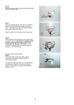
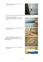
•
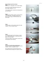
Transfer the check valve, together with the tube
from the check valve to the dispenser nozzle, to
the new door.
•
Reconnect the hose at the check valve. This
valve maintains a positive pressure in the water
tank and water discharge system.
NOTE:
The hose may need to be trimmed on the
end to prevent leaks.
Ensure that the hose is clipped into position
correctly.
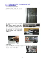
•
Refit the LCD housing, ensuring that the wiring
harness is firmly in place and is not preventing
the housing from closing.
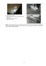
•
Refit the hinge bush and guide arm.
NOTE:
The tape mark on the bottom of harness
guide arm gives the correct amount of wire length
under the hinge cover to couple to the edge
connector. The lay of the harness in relationship
to the water tube is important to prevent fatigue of
the wiring harness. The wiring harness should
have the same loop length as the water tube and
sit underneath the tube.
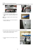
•
Refit the hinge bracket and the wiring harness
edge connector.
•
Check that the door is even and sealing correctly
all around.
•
Refit the water tube and harness to the guide
assembly.
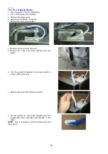
•
Refit the cabinet hinge cover.
•
Refit the hinge cover trim to the top of the door as
shown, applying even pressure to the clips when
re-assembling otherwise they may break.
Summary of Contents for 635 Active Smart
Page 1: ...321144 Service Manual 635 680 790 900 Active Smart Refrigerator Freezer R134a R600a Systems...
Page 2: ...321144 2...
Page 96: ...321144 96 Photo 12 22 5...
Page 100: ...321144 100 Diagram 12 25...
Page 108: ...321144 108 13 11 Embraco Compressor Fitted With External Overload Diagram 13 11...
Page 114: ...321144 114 14 2 Non Ice Water Models Wiring Diagram...
Page 116: ...321144 116 14 4 Ice Water Models Wiring Diagram...
Page 117: ...321144 117 14 5 900 Models Power Control Module Wiring Connections Reciprocating Compressor...
Page 118: ...321144 118 14 6 900 Models Wiring Diagram Reciprocating Compressor...
Page 119: ...321144 119 14 7 900 Models Power Control Module Wiring Connections VC Compressor...
Page 120: ...321144 120 14 8 900 Models Wiring Diagram VC Compressor...
Page 121: ...321144 121 14 9 B Model Wiring Route Diagram 14 9...
Page 122: ...321144 122 14 10 T Model Wiring Route Diagram 14 10...
Page 145: ......


