


321144
47
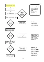
Is insulation
between
windings and
case OK?
Compressor system fault suspected.
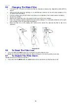
Disconnect power from the
appliance.
Measure compressor winding
resistance between phases
Megger test between compressor
windings and compressor case.
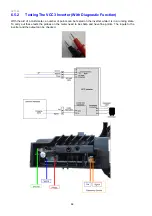
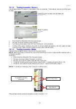
Measure VCC Signal and VCC
Mains harnesses for continuity and
inspect connectors for damage.
Are wires
continuous
and
connectors
undamaged?
With the refrigerator plugged in and
running, unplug the VCC Signal
harness and measure the frequency
of the signal.
Is signal
between
50Hz and
150Hz?
Are winding
resistances
OK?
(Refer Section 1
for compressor
specifications).
Compressor windings
damaged. Replace
compressor with new part.
Harness damaged.
Replace harness with new
part.
Suspect power/control
module. Replace
power/control module with
new part and test.
Suspect inverter module.
Replace inverter module
with new part and test.
No
No
No
No
Yes
Yes
Yes
Yes
Note:
A damaged
compressor could cause
damage to the inverter
module. If the compressor
windings are damaged, the
inverter may need to be
replaced as well.
Note:
A damaged harness
could cause damage to the
inverter module. If the
harness wires have shorted
to each other or to the
refrigerator chassis, the
inverter may need to be
replaced as well.
Note:
Damage to the
power/control module
which leaves all other
functions of the refrigerator
working correctly but the
compressor not running is
unlikely, but not impossible.
Please double-check that
there is no fault in the
inverter, compressor or
wiring before replacing the
power/control module.
Equipment Required
•
Multimeter with
resistance (
Ω
) scale
and frequency (Hz)
scale.
•
Insulation tester
(“megger”).
•
Spare VCC Inverter.
Summary of Contents for 635 Active Smart
Page 1: ...321144 Service Manual 635 680 790 900 Active Smart Refrigerator Freezer R134a R600a Systems...
Page 2: ...321144 2...
Page 96: ...321144 96 Photo 12 22 5...
Page 100: ...321144 100 Diagram 12 25...
Page 108: ...321144 108 13 11 Embraco Compressor Fitted With External Overload Diagram 13 11...
Page 114: ...321144 114 14 2 Non Ice Water Models Wiring Diagram...
Page 116: ...321144 116 14 4 Ice Water Models Wiring Diagram...
Page 117: ...321144 117 14 5 900 Models Power Control Module Wiring Connections Reciprocating Compressor...
Page 118: ...321144 118 14 6 900 Models Wiring Diagram Reciprocating Compressor...
Page 119: ...321144 119 14 7 900 Models Power Control Module Wiring Connections VC Compressor...
Page 120: ...321144 120 14 8 900 Models Wiring Diagram VC Compressor...
Page 121: ...321144 121 14 9 B Model Wiring Route Diagram 14 9...
Page 122: ...321144 122 14 10 T Model Wiring Route Diagram 14 10...
Page 145: ......


