


321144
35
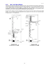
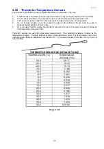
4.22 Thermistor Temperature Sensors
These sensors are used to monitor temperatures within the refrigerator. They are:
1.
A defrost sensor mounted above the evaporator used to measure the temperature when in defrost.
2.
An FC sensor mounted on the evaporator coil cover used to measure the temperature in FC.
3.
A PC sensor mounted in the PC on the duct cover and used to sense the PC temperature.
4.
On ice & water models, an ice tray sensor mounted on the bottom of the ice cube tray used to
measure the temperature of the ice tray.
5.
On ice & water models, a water tank sensor mounted at the rear of the water tank used to measure
the temperature of the water tank.
Thermistor sensors are used for temperature measurement. Their electrical resistance changes as the
temperature changes. The table below lists some typical resistance values. The temperature can be read
using Diagnostic Mode as described in the Section 10.1.5 (ice & water models) or Section 10.2.3 (non-ice &
water models).
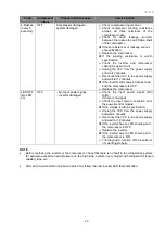
THERMISTOR SENSOR RESISTANCE TABLE
TEMPERATURE (
°
C)
RESISTANCE
(K Ohms
±
5%)
-30.0
25.17
-25.0
19.43
-20.0
15.13
-15.0
11.88
-10.0
9.392
-5.0
7.481
0.0
6.000
5.0
4.844
10.0
3.935
15.0
3.217
20.0
2.644
25.0
2.186
30.0
1.817
35.0
1.518
40.0
1.274
45.0
1.075
50.0
0.9106
Diagram 4.22
Summary of Contents for 635 Active Smart
Page 1: ...321144 Service Manual 635 680 790 900 Active Smart Refrigerator Freezer R134a R600a Systems...
Page 2: ...321144 2...
Page 96: ...321144 96 Photo 12 22 5...
Page 100: ...321144 100 Diagram 12 25...
Page 108: ...321144 108 13 11 Embraco Compressor Fitted With External Overload Diagram 13 11...
Page 114: ...321144 114 14 2 Non Ice Water Models Wiring Diagram...
Page 116: ...321144 116 14 4 Ice Water Models Wiring Diagram...
Page 117: ...321144 117 14 5 900 Models Power Control Module Wiring Connections Reciprocating Compressor...
Page 118: ...321144 118 14 6 900 Models Wiring Diagram Reciprocating Compressor...
Page 119: ...321144 119 14 7 900 Models Power Control Module Wiring Connections VC Compressor...
Page 120: ...321144 120 14 8 900 Models Wiring Diagram VC Compressor...
Page 121: ...321144 121 14 9 B Model Wiring Route Diagram 14 9...
Page 122: ...321144 122 14 10 T Model Wiring Route Diagram 14 10...
Page 145: ......


