


321144
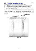
40
6
VARIABLE CAPACITY COMPRESSOR
Some Active Smart
®
refrigerators are fitted with variable capacity compressors (VCC) depending on the
model and market. The compressor is turned on when cooling is required and is switched by the
power/control module sending a low voltage frequency signal to the inverter.
The VCC improves energy efficiency and maintains a more stable temperature in both the provision
compartment and the freezer compartment. The compressor windings are wired in a 3 phase star formation
with the resistance between any two pins being the same (6.4 ohms).
6.1
Variable Capacity Compressor Control Overview
The power/control module on VCC product is identical to that on non-VCC product. The power/control
module senses if it is connected to a VCC compressor and uses the appropriate algorithm.
The compressor can operate at speeds between 1590 and 4300 rpm inclusive. On the Fisher & Paykel
product we operate the compressor at a select number of different speeds between 1590 and 4300 rpm to
reduce the variation in sound produced by the compressor. An electronic module/inverter connected
between the power/control module and the compressor controls the speed. This it does by supplying a
modulated DC 3 phase supply to the compressor.
Warning: Permanent damage will occur if the
compressor is directly connected to the AC supply line.
The power/control module monitors, amongst other things, the refrigerator compartment temperatures (via
thermistors) and the defrost cycle, and from this information sends signals to the electronic module/inverter
to determine compressor speeds.
Whenever the compressor starts, it is run at 2200 rpm for 2.5 seconds to establish lubrication, and is then
run at 1590 rpm for a further 27 seconds before changing to any other higher speed as requested by the
power/control module. This is to provide a softer start before the compressor potentially ramps up to some
higher speed.
Whenever the refrigerator is plugged in/turned on, and/or after a defrost, in the first cooling cycle the control
will run the compressor, after its initial start procedure, at its maximum speed, which is 4300 rpm. The
compressor will stay at its maximum speed until both compartments have reached their cut-out temperature,
at which point the compressor will switch off and the refrigerator goes into the warm-up cycle.
In the subsequent cooling cycles, the algorithm will vary the compressor speed according to the amount of
cooling required to achieve an average temperature in each compartment (as measured by the thermistors),
equal to the compartment set temperatures with a 1 hour run-time.
In low ambient, where the heat load and/or cabinet usage is low, the compressor will be likely to run at its
minimum speed (1590rpm), and switch off more frequently than once every hour, similar to most non-VCC
product.
When the compressor is running at slow speeds, the evaporator may not be fully flooded, but this is normal.
6.2
Built-in Electronic Protections (Within the
Module/Inverter)
6.2.1
Compressor Start-up
In case any anomaly occurs during compressor starting, the control will wait 6 seconds before repeating the
start-up. If the compressor doesn’t start after 12 trials, the control will wait 8 minutes before repeating the
start-up procedure (this condition may be when pressures are not equalised between suction and discharge
sides in the refrigeration system, eg; after an interruption in the mains supply).
6.2.2
Overload Detection and Protection
The control can detect an overload condition by monitoring the current consumed by the compressor. If
overload is detected, the control reduces the current by reducing the speed of the compressor until the
overload disappears, when the speed will return to the required value.
If the overload increases, the control will continue to decrease the current until the minimum speed of 1590
rpm may be reached, at which point the compressor may “stall”, and the control will return to the start-up
procedure.
Summary of Contents for 635 Active Smart
Page 1: ...321144 Service Manual 635 680 790 900 Active Smart Refrigerator Freezer R134a R600a Systems...
Page 2: ...321144 2...
Page 96: ...321144 96 Photo 12 22 5...
Page 100: ...321144 100 Diagram 12 25...
Page 108: ...321144 108 13 11 Embraco Compressor Fitted With External Overload Diagram 13 11...
Page 114: ...321144 114 14 2 Non Ice Water Models Wiring Diagram...
Page 116: ...321144 116 14 4 Ice Water Models Wiring Diagram...
Page 117: ...321144 117 14 5 900 Models Power Control Module Wiring Connections Reciprocating Compressor...
Page 118: ...321144 118 14 6 900 Models Wiring Diagram Reciprocating Compressor...
Page 119: ...321144 119 14 7 900 Models Power Control Module Wiring Connections VC Compressor...
Page 120: ...321144 120 14 8 900 Models Wiring Diagram VC Compressor...
Page 121: ...321144 121 14 9 B Model Wiring Route Diagram 14 9...
Page 122: ...321144 122 14 10 T Model Wiring Route Diagram 14 10...
Page 145: ......


