


321144
90
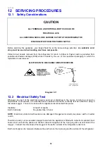
12.4.1 Initialisation Of The Power/Control Module After Installation –
Non-Ice & Water Models
The power/control module needs to know whether it is fitted into a “B” or “T” model upon installation because
it needs to turn on the interior light, and to identify the PC and FC compartments for the selected
temperature settings.
To initialise, the serviceperson must have the FC door closed, the PC door open and then press any of the
buttons on the user interface in the PC. This will initialise the module for the cabinet it is fitted into. Until
then, the interior light may not turn on, indicating that the power/control module has not been initialised.
If the power/control module is moved from one cabinet to another and the model option is wrong, the PC
light will turn on only when the FC door is opened. Initialise the power/control module as described in the
previous paragraph.
If the power/control module is not initialised, as may be the situation for a new service module, the lights will
not turn on. If the operator presses a button with both doors opened, the illegal
raspberry
audible feedback
will sound, indicating that the module is unable to be initialised. The service installation document, which is
included with the new service module, will give instructions on the initialisation of the module.
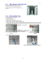
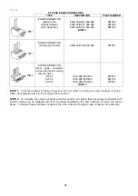
12.5 Freezer Bin, Runner and Air Deflector Removal - E402B
and E372B Models
1. Disconnect the refrigerator from the power supply.
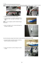
2. Remove the top shelf by lifting the rear of the shelf to release it from its locked position and slide the
shelf forward.
3. Remove the limit stops from the top rear edge of the plastic bins and slide the bins out of the runners.
4. The runners must be in the fully retracted position. Twist and rotate the inner runner upwards to release
it from the outer runner.
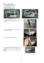
5. Pull the inner runner forward, sliding out of the outer runner to remove.
6. To remove the outer runner, gently lever out the small lock clip with a small screwdriver.
7. Carefully slide the runner out of the FC liner.
8. Remove the air deflector by pushing in towards the centre to bow the deflector slightly. This will cause
the clip legs to disengage from the front cover and allow the deflector to be removed.
9. Refit in reverse order.
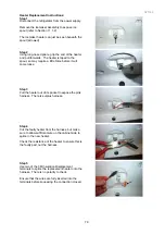
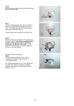
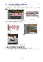
12.6 FC Bin Removal - 900 Models
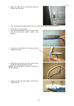
1. Open the FC drawer and remove all ice and storage bins.
2. Remove the safety clip from the tray. (Refer photo 12.6)
Remove safety clip from slide
to remove tray.
3. Remove the tray.
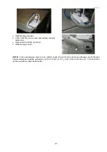
4. To remove the bin, pull it back towards the freezer.
5. Lift the front of the bin and turn the bin 90
O
and remove from the FC.
6. Refit the bins in reverse order.
Summary of Contents for 635 Active Smart
Page 1: ...321144 Service Manual 635 680 790 900 Active Smart Refrigerator Freezer R134a R600a Systems...
Page 2: ...321144 2...
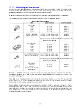
Page 96: ...321144 96 Photo 12 22 5...
Page 100: ...321144 100 Diagram 12 25...
Page 108: ...321144 108 13 11 Embraco Compressor Fitted With External Overload Diagram 13 11...
Page 114: ...321144 114 14 2 Non Ice Water Models Wiring Diagram...
Page 116: ...321144 116 14 4 Ice Water Models Wiring Diagram...
Page 117: ...321144 117 14 5 900 Models Power Control Module Wiring Connections Reciprocating Compressor...
Page 118: ...321144 118 14 6 900 Models Wiring Diagram Reciprocating Compressor...
Page 119: ...321144 119 14 7 900 Models Power Control Module Wiring Connections VC Compressor...
Page 120: ...321144 120 14 8 900 Models Wiring Diagram VC Compressor...
Page 121: ...321144 121 14 9 B Model Wiring Route Diagram 14 9...
Page 122: ...321144 122 14 10 T Model Wiring Route Diagram 14 10...
Page 145: ......


