


321144
123
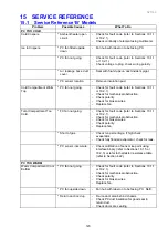
15 SERVICE REFERENCE
15.1 Service Reference ‘B’ Models
Problem
Possible Causes
What To Do
PC TOO COLD
Cold Crispers.
* Ambient heater open
circuit.
- Check for fault code (refer to Sections 10.1.1
or 10.2.1).
- Check continuity of element using multimeter.
Ice In Crispers.
* PC fan fitted upside
down.
- Fan hub with label on to be facing PC.
* PC fan not going.
-
Check for fault code (refer to Sections 10.1.1
-
Check voltage to plug, check wiring polarity.
* Air leakage base duct
cover.
- Seal with foam tape on duct divider spigot.
* PC sensor location.
- Remove insulation pad.
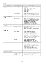
Cold Compartment Warm
Top.
* PC fan not going.
- Check for fault code (refer to Sections 10.1.1
or 10.2.1).
- Check for mechanical obstruction.
- Check polarity.
- Check for broken wires.
- Replace fan.
Total Compartment Too
Cold.
* FC fan not going.
- Check for fault code (refer to Sections 10.1.1
or 10.2.1).
- Check for mechanical obstruction.
- Check for broken wires.
- Check polarity.
- Replace fan.
* Short of gas.
- Check run percentage, if high check
evaporator.
- Check fully flooded evaporator, check for leak.
* PC sensor inaccurate. - Check calibration of sensor ice point using
interface binary (refer to Sections 10.1.5 or
10.2.3) or refer to thermistor resistance table
(refer to Section 4.22).
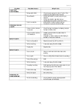
PC TOO WARM
Warm Compartment Cool
Bottom.
* PC fan not going.
- Check for fault code (refer to Sections 10.1.1
or 10.2.1).
- Check for mechanical obstruction.
- Check polarity.
- Check for broken wires.
- Replace fan.
* PC fan upside down.
- Fan hub with label on to be facing PC. Refit.
* Return duct iced up.
- De-ice duct area behind chassis.
- Check PC duct insulation for good seal in
return duct.
- Check doors are sealing.
Summary of Contents for 635 Active Smart
Page 1: ...321144 Service Manual 635 680 790 900 Active Smart Refrigerator Freezer R134a R600a Systems...
Page 2: ...321144 2...
Page 96: ...321144 96 Photo 12 22 5...
Page 100: ...321144 100 Diagram 12 25...
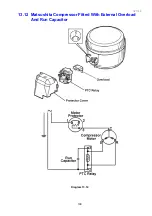
Page 108: ...321144 108 13 11 Embraco Compressor Fitted With External Overload Diagram 13 11...
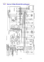
Page 114: ...321144 114 14 2 Non Ice Water Models Wiring Diagram...
Page 116: ...321144 116 14 4 Ice Water Models Wiring Diagram...
Page 117: ...321144 117 14 5 900 Models Power Control Module Wiring Connections Reciprocating Compressor...
Page 118: ...321144 118 14 6 900 Models Wiring Diagram Reciprocating Compressor...
Page 119: ...321144 119 14 7 900 Models Power Control Module Wiring Connections VC Compressor...
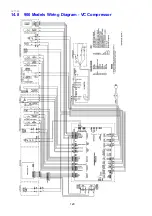
Page 120: ...321144 120 14 8 900 Models Wiring Diagram VC Compressor...
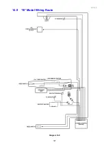
Page 121: ...321144 121 14 9 B Model Wiring Route Diagram 14 9...
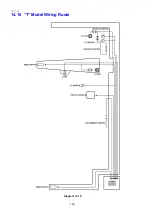
Page 122: ...321144 122 14 10 T Model Wiring Route Diagram 14 10...
Page 145: ......


