
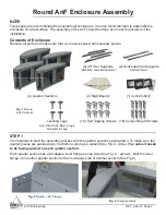
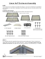
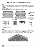

AnF Enclosures
REV. 8-29-18 Page 9
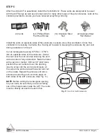
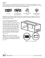
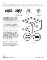
STEP 5
After the entire AnF is assembled, install the Vent-Kit-6x12. These vents are designed to be used
with the AnF Series as well as universal vents for many other types of fi re pit enclosures. Look at the
contents provided to ensure you have received everything correctly.
Install the vents on opposite sides of the enclosure to ensure cross fl ow ventilation. Cross fl ow
ventilation is necessary to provide free fl owing air to assist in keeping the enclosure dry and cool
during operation of a fi re pit.
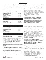
Cut an rectangular opening 9.750”w x
3.750”h into on opposite sides of the
enclosure. Center the vent over the cut out
area ensuring the vent slots are clear of any
obstruction. Mark the holes with a pencil
or marker. Drill six 1⁄4” pilot holes, position
the vent centered over the opening, insert
a screw into the vent and enclosure at the
same time and secure with washer and
nut on the inside. Repeat the process until
all six screws are securing each vent into
place on both sides of the AnF enclosure
(See Fig. 21).
CUT OUT DETAIL
9.750”
3.750”
Fig. 21
Vent Cut Out Dimensions
(2) Vents
(12) Phillips Black
Pan Head Screw
(12) Stainless Steel
Nut
(2) Stainless Steel
Flat Washer
NOTE:
Before cutting the rectangular
opening for your vents, be sure that you are
not hitting one of the metal studs inside the
AnF. The vents must be directly across from
each other.


