


53
REV. 00 02/01/2015
id.:
CBV ADVANCED
MODE FUNCTIONS
3
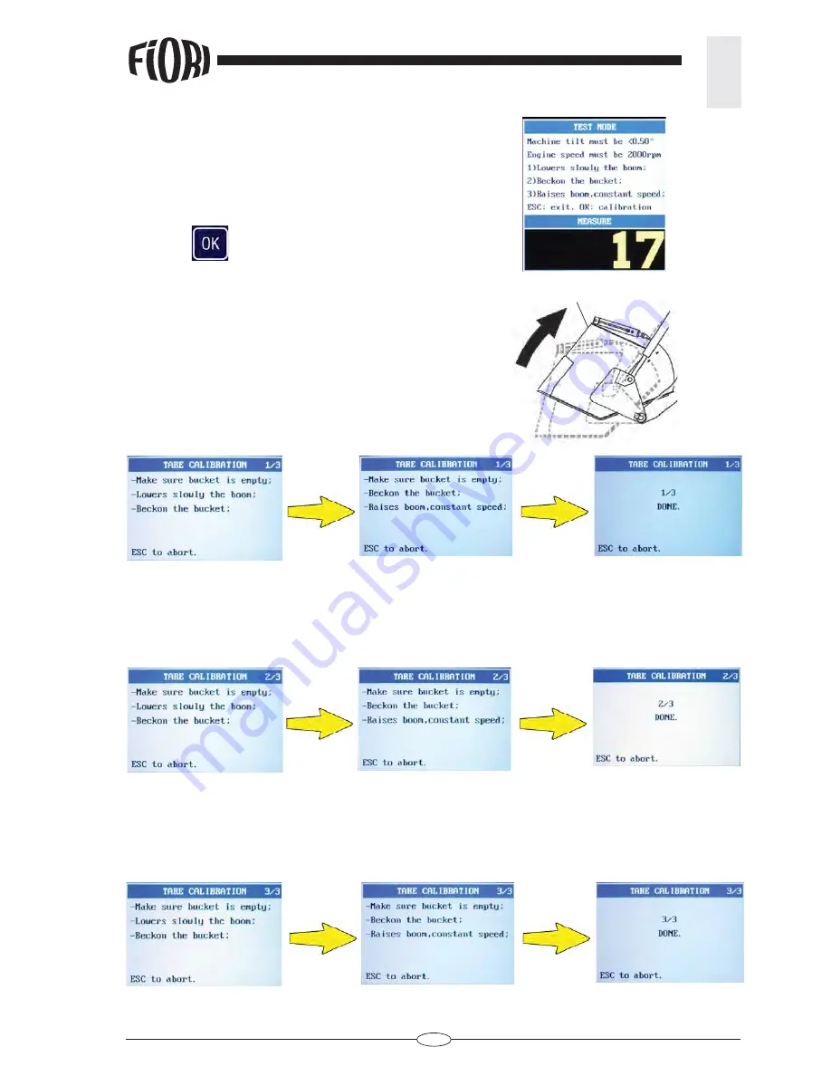
TEST
1) Slowly lower the boom
2) Withdraw the bucket (A)
3) Lift the boom back up at a constant speed.
If the value displayed differs from zero (60 in this
instance), then the tare needs to be calibrated.
- Press OK
to shift to the calibration mode
TARE CALIBRATION
Step 1/3
- Ensure that the bucket is empty
- Slowly lower the boom
- Withdraw the bucket (A)
- Lift the boom at a constant speed
Step 2/3
- Check that the bucket is empty
- Slowly lower the boom
- Withdraw the bucket (A)
- Lift the boom back up
Step 3/3
- Check that the bucket is empty
- Slowly lower the boom
- Withdraw the bucket (A)
- Lift the boom back up
If during calibration the device detects any faults, it will ask to repeat the 3 calibration steps
.
A


