EX355
W5-3-1
ENGINE OVERHAUL
SERVICE PRECAUTIONS
•
Be sure to use the correct fastener in the proper
location. If a used fastener is replaced with a new
one, the new fastener must be identical to the
previous one.
•
Some fasteners must always be replaced with
new ones following removal. These fasteners are
specified in this Manual.
•
Some fasteners require thread locker or thread
sealant. These fasteners are specified in this
Manual.
•
Supplemental fastener coatings (paint, grease, or
corrosion inhibitor) affect fastener torque and
clamping force. They may damage the fastener.
Do not use them unless specifically called for.
•
Tighten all fasteners to the specified torque. If
there is a tightening sequence, follow it exactly.
GENERAL DESCRIPTION
Engine Cleanliness and Care
•
An industrial engine is a combination of many
machines that have been honed and polished.
Tolerances are measured in 1,000
ths
of millimeters
(10,000
ths
of inches).
•
When servicing engine assemblies and parts,
care and cleanliness are extremely important.
Proper cleaning and the protection of friction areas
and delicate parts are part of the service proce-
dure.
•
Apply engine oil to all friction areas during
reassembly to provide protection and lubrication
when the engine is started.
•
When valve train components, pistons, piston
rings, connecting rods, connecting rod bearings,
and crankshaft bearings are removed, they must
be reinstalled to their original positions. To ensure
this, mark the parts at disassembly and store them
neatly.
•
Disconnect battery cables before working on the
engine. This prevents damage to wire harnesses
and other electrical parts.
•
Engine cylinders are numbered 1-2-3-4-5-6 from
the front of the engine (crankshaft pulley) to the
rear (flywheel).
Engine Service (General information)
Read the following carefully to avoid engine damage
and ensure reliable engine performance and a long
service life.
•
The 12-Volt electrical system is capable of damag-
ing delicate electrical circuits. Be absolutely cer-
tain that the ground cable is disconnected at the
battery when servicing the engine.
•
After removing the intake air duct or air cleaner,
immediately cover the intake opening with a clean
cloth. This prevents the entry of foreign material
capable of causing serious engine damage.
Engine Components
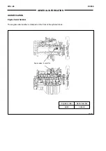
The 6HK1 engine is a 4-cycle, 6-cylinder in-line,
diesel engine with direct fuel injection. Engine dis-
placement is 7.79 liters (475 cubic inches).
The engine uses a gear-driven overhead camshaft
timing train.
The engine is quiet, economical, and durable.
Cylinder Head
The cross-flow cylinder head is constructed of cast
iron. The intake system is at the left side of the engine
and the exhaust system is at the right side. This
configuration reduces resistance in the two systems.
A laminated cylinder head gasket is used to minimize
fatigue. The head and gasket are secured to the block
using the angular tightening method. This provides a
reliable seal against gas and water leakage.
Cylinder Block and Cylinder Liners
The cast iron cylinder block has 7 bearings. Bearing
caps have a ladder frame construction to integrate
them with the crankcase and increase engine rigidity.
Cylinder liners are constructed of very thin, special-
use iron alloys. In combination with the chrome-plated
1
st
and 3
rd
piston rings, they provide excellent wear
resistance.
Pistons
The aluminum alloy pistons have a ring trigger cast
into the 1
st
ring groove. The outer sliding surface of the
1
st
and 3
rd
piston rings are chrome plated to provide
strength and wear resistance.
Crankshaft
The forged steel crankshaft is soft nitride treated for
additional strength. The 7 bearings together with the
4 counterweights result in reduced bearing rotational
load.
Gear Train
The gear train is at the rear of the engine (flywheel
side). This minimizes torsion vibration from the crank-
shaft and reduces noise.
To further reduce noise, the crankshaft gear is
shrinkfitted to the crankshaft. Precise gear arrange-
ment, gear ratio, backlash, and bearing rigidity also
contribute to a quieter engine.
Summary of Contents for EX355 Tier2
Page 22: ...T1 2 10 EX355 COMPONENT LAYOUT NOTES ...
Page 37: ...T2 1 14 EX355 CONTROL SYSTEM NOTES ...
Page 47: ...T2 2 10 EX355 HYDRAULIC SYSTEM NOTES ...
Page 73: ...T2 3 26 EX355 ELECTRICAL SYSTEM NOTES ...
Page 86: ...T3 1 12 EX355 PUMP DEVICE NOTES ...
Page 94: ...T3 2 8 EX355 SWING DEVICE NOTES ...
Page 134: ...T3 4 10 EX355 PILOT VALVE NOTES ...
Page 146: ...T3 5 12 EX355 TRAVEL DEVICE NOTES ...
Page 156: ...T3 7 4 EX355 OTHER COMPONENTS Undercarriage NOTES ...
Page 195: ...T4 2 6 EX355 STANDARD NOTES ...
Page 199: ...T4 3 4 EX355 ENGINE TEST NOTES ...
Page 215: ...T4 4 16 EX355 EXCAVATOR TEST NOTES ...
Page 237: ...T4 5 22 EX355 COMPONENT TEST NOTES ...
Page 265: ...T5 2 12 EX355 COMPONENT LAYOUT NOTES ...
Page 325: ...T5 4 52 EX355 TROUBLESHOOTING B ...
Page 372: ...EX355 T5 6 9 ELECTRICAL SYSTEM INSPECTION ...
Page 385: ...T5 6 22 EX355 ELECTRICAL SYSTEM INSPECTION NOTE ...
Page 425: ...W1 1 4 EX355 PRECAUTIONS FOR DISASSEMBLY AND ASSEMBLY NOTES ...
Page 450: ...W2 3 8 EX355 MAIN FRAME NOTES ...
Page 454: ...W2 4 4 EX355 PUMP DEVICE SM5510 ...
Page 456: ...W2 4 6 EX355 PUMP DEVICE SM5510 ...
Page 458: ...W2 4 8 EX355 PUMP DEVICE ASSEMBLE PUMP DEVICE SM6205 SM6206 ...
Page 460: ...W2 4 10 EX355 PUMP DEVICE SM6205 SM6206 ...
Page 462: ...W2 4 12 EX355 PUMP DEVICE SM6205 SM6206 ...
Page 464: ...W2 4 14 EX355 PUMP DEVICE SM6205 SM6206 ...
Page 468: ...W2 4 18 EX355 PUMP DEVICE SM6210 ...
Page 470: ...W2 4 20 EX355 PUMP DEVICE SM6210 ...
Page 472: ...W2 4 22 EX355 PUMP DEVICE SM6210 ...
Page 474: ...W2 4 24 EX355 PUMP DEVICE SM5511 SM6219 ASSEMBLE MAIN PUMP ...
Page 476: ...W2 4 26 EX355 PUMP DEVICE SM5511 SM6219 ...
Page 478: ...W2 4 28 EX355 PUMP DEVICE SM5511 SM6219 ...
Page 480: ...W2 4 30 EX355 PUMP DEVICE SM5511 SM6219 ...
Page 482: ...W2 4 32 EX355 PUMP DEVICE SM5511 SM6219 ...
Page 484: ...W2 4 34 EX355 PUMP DEVICE SM5511 SM6219 ...
Page 486: ...W2 4 36 EX355 PUMP DEVICE SM5511 SM6219 ...
Page 498: ...W2 4 48 EX355 PUMP DEVICE NOTES ...
Page 532: ...W2 5 34 EX355 CONTROL VALVE NOTES ...
Page 540: ...W2 6 8 EX355 SWING DEVICE SM6277 31 18 17 20 19 21 3 24 27 25 26 10 ...
Page 542: ...W2 6 10 EX355 SWING DEVICE SM6277 31 19 2 1 23 22 ...
Page 566: ...W2 7 12 EX355 PILOT VALVE 11 19 17 18 1 2 3 8 13 14 16 15 SM1114 ...
Page 572: ...W2 7 18 EX355 PILOT VALVE 8 6 7 1 3 4 5 9 21 2 SM1119 ...
Page 586: ...W2 7 32 EX355 PILOT VALVE NOTES ...
Page 592: ...W2 8 6 EX355 PILOT SHUT OFF VALVE NOTES ...
Page 602: ...W2 10 6 EX355 SOLENOID VALVE UNIT NOTES ...
Page 621: ...W3 2 10 EX355 TRAVEL DEVICE SM5108 44 8 13 12 1 45 46 28 27 25 26 24 36 38 30 31 32 ...
Page 627: ...W3 2 16 EX355 TRAVEL DEVICE SM5502 3 4 5 20 7 8 9 10 12 14 13 16 11 6 ...
Page 643: ...W3 2 32 EX355 TRAVEL DEVICE NOTES ...
Page 651: ...W3 3 8 EX355 CENTER JOINT NOTES ...
Page 655: ...W3 4 4 EX355 TRACK ADJUSTER 8 14 13 11 17 12 SM6284 ...
Page 657: ...W3 4 6 EX355 TRACK ADJUSTER 3 4 8 10 16 15 14 SM6284 ...
Page 659: ...W3 4 8 EX355 TRACK ADJUSTER 3 6 4 8 10 9 SM6284 18 ...
Page 667: ...W3 4 16 EX355 TRACK ADJUSTER NOTES ...
Page 671: ...W3 5 4 EX355 FRONT IDLER 1 SM6290 2 4 3 5 6 8 12 7 6 3 4 1 2 9 10 11 ...
Page 689: ...W3 6 14 EX355 UPPER AND LOWER ROLLER NOTES ...
Page 708: ...W4 1 10 EX355 FRONT ATTACHMENT NOTES ...
Page 716: ...W4 1 18 EX355 FRONT ATTACHMENT NOTES ...
Page 744: ...W4 2 28 EX355 CYLINDERS NOTES ...
Page 763: ...EX355 W5 1 17 GENERAL INFORMATION Oil Pan N m kgf m Ib ft SM7010 ...
Page 765: ...EX355 W5 1 19 GENERAL INFORMATION Water Pump N m kgf m Ib ft SM7012 ...
Page 815: ...EX355 W5 3 35 ENGINE OVERHAUL Disassembly SM7093 1 Camshaft gear 2 Knock pin 3 Camshaft ...
Page 883: ...EX355 W5 3 103 ENGINE OVERHAUL Reassembly 1 Crankshaft 3 Crankshaft gear 2 Pin SM7239 ...
Page 894: ...W5 3 114 EX355 ENGINE OVERHAUL NOTE ...
Page 938: ...W5 7 6 EX355 ENGINE INDUCTION NOTE ...


