W5-1-2
EX355
GENERAL INFORMATION
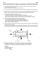
18. Test fluid from the injection nozzle tester will spray out of the injection nozzle under great pressure.
It can easily puncture a person's skin.
Keep your hands away from the injection nozzle at all times.
19. Do not use your fingers to feel for fuel leaks at fittings. Fuel pressure is high enough to penetrate the skin.
20. Be careful when changing fuel system components: Diesel fuel is flammable. Be sure that the ignition key of
OFF. Do not smoke or allow open flame in the area while changing fuel system components.
21. Measurements are indicated by “standard” or “limit”:
- a “standard” value refers to the standard values at time of assembly;
- a “limit” value is a maximum or minimum: measurements up to that value are usable.
Measurement falling beyond that value mean the part must be serviced, adjusted, or replaced.
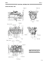
22. Directional indications adopted within this manual are as follows:
- Front: Toward the cooling fan when viewed from the flywheel side;
- Left: Toward the fuel injection pump when viewed from the flywheel side;
- Right: Toward the exhaust manifold when viewed from the flywheel side;
- Rear: Toward the engine’s flywheel side.
23. “Cylinder numbers” and “Engine rotation direction”: Cylinder numbers are counted in sequence beginning
from the front side of the engine.
As a result, the first cylinder at the very front of the engine is cylinder No. 1, while the last cylinder toward the
rear is cylinder No. 6. The direction of engine rotation is clockwise when viewed from the cooling fan side.
24. Maintenance procedure call for use of Special or Commercial Tools, where necessary.
The Special Tools required or recommended are identified by an ISUZU Part Number.
Any Special Tools are available in Europe making a purchase order to the following:
IED MAESA
BOOMSESTENWEG 42B
2630 AARTSELAAR
BELGIUM
Flywheel
Rear
Front
Right
Left
Exhaust manifold
Cooling fan
Summary of Contents for EX355 Tier2
Page 22: ...T1 2 10 EX355 COMPONENT LAYOUT NOTES ...
Page 37: ...T2 1 14 EX355 CONTROL SYSTEM NOTES ...
Page 47: ...T2 2 10 EX355 HYDRAULIC SYSTEM NOTES ...
Page 73: ...T2 3 26 EX355 ELECTRICAL SYSTEM NOTES ...
Page 86: ...T3 1 12 EX355 PUMP DEVICE NOTES ...
Page 94: ...T3 2 8 EX355 SWING DEVICE NOTES ...
Page 134: ...T3 4 10 EX355 PILOT VALVE NOTES ...
Page 146: ...T3 5 12 EX355 TRAVEL DEVICE NOTES ...
Page 156: ...T3 7 4 EX355 OTHER COMPONENTS Undercarriage NOTES ...
Page 195: ...T4 2 6 EX355 STANDARD NOTES ...
Page 199: ...T4 3 4 EX355 ENGINE TEST NOTES ...
Page 215: ...T4 4 16 EX355 EXCAVATOR TEST NOTES ...
Page 237: ...T4 5 22 EX355 COMPONENT TEST NOTES ...
Page 265: ...T5 2 12 EX355 COMPONENT LAYOUT NOTES ...
Page 325: ...T5 4 52 EX355 TROUBLESHOOTING B ...
Page 372: ...EX355 T5 6 9 ELECTRICAL SYSTEM INSPECTION ...
Page 385: ...T5 6 22 EX355 ELECTRICAL SYSTEM INSPECTION NOTE ...
Page 425: ...W1 1 4 EX355 PRECAUTIONS FOR DISASSEMBLY AND ASSEMBLY NOTES ...
Page 450: ...W2 3 8 EX355 MAIN FRAME NOTES ...
Page 454: ...W2 4 4 EX355 PUMP DEVICE SM5510 ...
Page 456: ...W2 4 6 EX355 PUMP DEVICE SM5510 ...
Page 458: ...W2 4 8 EX355 PUMP DEVICE ASSEMBLE PUMP DEVICE SM6205 SM6206 ...
Page 460: ...W2 4 10 EX355 PUMP DEVICE SM6205 SM6206 ...
Page 462: ...W2 4 12 EX355 PUMP DEVICE SM6205 SM6206 ...
Page 464: ...W2 4 14 EX355 PUMP DEVICE SM6205 SM6206 ...
Page 468: ...W2 4 18 EX355 PUMP DEVICE SM6210 ...
Page 470: ...W2 4 20 EX355 PUMP DEVICE SM6210 ...
Page 472: ...W2 4 22 EX355 PUMP DEVICE SM6210 ...
Page 474: ...W2 4 24 EX355 PUMP DEVICE SM5511 SM6219 ASSEMBLE MAIN PUMP ...
Page 476: ...W2 4 26 EX355 PUMP DEVICE SM5511 SM6219 ...
Page 478: ...W2 4 28 EX355 PUMP DEVICE SM5511 SM6219 ...
Page 480: ...W2 4 30 EX355 PUMP DEVICE SM5511 SM6219 ...
Page 482: ...W2 4 32 EX355 PUMP DEVICE SM5511 SM6219 ...
Page 484: ...W2 4 34 EX355 PUMP DEVICE SM5511 SM6219 ...
Page 486: ...W2 4 36 EX355 PUMP DEVICE SM5511 SM6219 ...
Page 498: ...W2 4 48 EX355 PUMP DEVICE NOTES ...
Page 532: ...W2 5 34 EX355 CONTROL VALVE NOTES ...
Page 540: ...W2 6 8 EX355 SWING DEVICE SM6277 31 18 17 20 19 21 3 24 27 25 26 10 ...
Page 542: ...W2 6 10 EX355 SWING DEVICE SM6277 31 19 2 1 23 22 ...
Page 566: ...W2 7 12 EX355 PILOT VALVE 11 19 17 18 1 2 3 8 13 14 16 15 SM1114 ...
Page 572: ...W2 7 18 EX355 PILOT VALVE 8 6 7 1 3 4 5 9 21 2 SM1119 ...
Page 586: ...W2 7 32 EX355 PILOT VALVE NOTES ...
Page 592: ...W2 8 6 EX355 PILOT SHUT OFF VALVE NOTES ...
Page 602: ...W2 10 6 EX355 SOLENOID VALVE UNIT NOTES ...
Page 621: ...W3 2 10 EX355 TRAVEL DEVICE SM5108 44 8 13 12 1 45 46 28 27 25 26 24 36 38 30 31 32 ...
Page 627: ...W3 2 16 EX355 TRAVEL DEVICE SM5502 3 4 5 20 7 8 9 10 12 14 13 16 11 6 ...
Page 643: ...W3 2 32 EX355 TRAVEL DEVICE NOTES ...
Page 651: ...W3 3 8 EX355 CENTER JOINT NOTES ...
Page 655: ...W3 4 4 EX355 TRACK ADJUSTER 8 14 13 11 17 12 SM6284 ...
Page 657: ...W3 4 6 EX355 TRACK ADJUSTER 3 4 8 10 16 15 14 SM6284 ...
Page 659: ...W3 4 8 EX355 TRACK ADJUSTER 3 6 4 8 10 9 SM6284 18 ...
Page 667: ...W3 4 16 EX355 TRACK ADJUSTER NOTES ...
Page 671: ...W3 5 4 EX355 FRONT IDLER 1 SM6290 2 4 3 5 6 8 12 7 6 3 4 1 2 9 10 11 ...
Page 689: ...W3 6 14 EX355 UPPER AND LOWER ROLLER NOTES ...
Page 708: ...W4 1 10 EX355 FRONT ATTACHMENT NOTES ...
Page 716: ...W4 1 18 EX355 FRONT ATTACHMENT NOTES ...
Page 744: ...W4 2 28 EX355 CYLINDERS NOTES ...
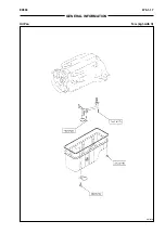
Page 763: ...EX355 W5 1 17 GENERAL INFORMATION Oil Pan N m kgf m Ib ft SM7010 ...
Page 765: ...EX355 W5 1 19 GENERAL INFORMATION Water Pump N m kgf m Ib ft SM7012 ...
Page 815: ...EX355 W5 3 35 ENGINE OVERHAUL Disassembly SM7093 1 Camshaft gear 2 Knock pin 3 Camshaft ...
Page 883: ...EX355 W5 3 103 ENGINE OVERHAUL Reassembly 1 Crankshaft 3 Crankshaft gear 2 Pin SM7239 ...
Page 894: ...W5 3 114 EX355 ENGINE OVERHAUL NOTE ...
Page 938: ...W5 7 6 EX355 ENGINE INDUCTION NOTE ...

