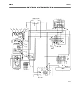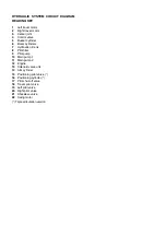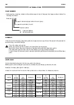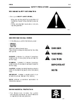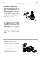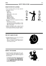
ELECTRICAL SYSTEM CIRCUIT DIAGRAM
READING KEY
1
Batteries
2
Battery relay
3
Starter motor
4
Starter relay
6
Key switch
7
Fuse link 2 (BOX A) 40 A
11
Horn button
14
Horn
15
Fuse link 1 (BOX A) 40 A
16
EC motor
17
Power outlet (24V 180W)
20
Windscreen wiper motor
21
Windscreen washer electrical pump
22
Cab light
23
Fuse box
24
Cab light relay (R5) (opt)
25
Radio
26
Cigar lighter
28
Upperstructure light
29
Boom light
32
Alternator
34
Fuse link 3 (BOX B) 60 A
35
Electrical fan and control for heater
39
Air filter restriction switch
40
Engine coolant overheat switch
41
Hydraulic oil level switch
42
Engine coolant level switch
43
Engine oil level sensor
44
Fuel level switch
45
Engine coolant temperature sensor
46
Low engine oil pressure switch
49
Rotary bucket solenoid valve provision (opt)
50
Rotary bucket switch (SW 3) (opt)
51
Diagnostic tester connector (Dr. EX)
52
Engine control dial
53
Main controller (MC)
54
E button (Economy mode)
55
H/P button (High-Power mode)
56
Engine speed control panel
59
Seat heating resistors and control (opt)
60
Electrical fuel lift pump (opt)
61
Engine speed control panel light
62
Optional equipment connector
63
Engine speed pedal provision connector
65
Hour-counter
66
Engine coolant temperature gauge
67
Fuel level gauge
68
Instrument panel lighting
69
Engine oil level indicator light
70
Engine coolant level indicator light
71
Hydraulic oil level indicator light
72
Alternator (Battery charge) indicator light
73
Engine oil low pressure indicator light
74
Overheat indicator light
75
Buzzer
76
Rotary bucket selector (opt)
77
Air filter restriction indicator light
78
Low fuel level indicator light
79
Windscreen wiper safety switch
80
EC sensor
81
Auto-idle engaged light (led)
82
E mode engaged light (led)
83
H/P mode engaged light (led)
84
Engine learning switch connector
85
Level check button (CHECK)
86
Buzzer stop button
87
Windscreen washer control button
88
Windscreen wiper control button
89
Lights control button
90
WORK MODE selector button
91
GENERAL PURPOSE work mode light (led)
92
GRADING work mode light (led)
93
PRECISION work mode light (led)
94
ATTACHMENT work mode light (led)
95
SI solenoid valve (travel motor swash angle control)
96
SG solenoid valve (Power boost control)
97
SD solenoid valve (Speed sensing control)
98
SC solenoid valve (Arm regenerative control)
100
Air conditioning system (opt)
101
Auto - idle control button
102
Engine speed sensor (N)
103
Pump 2 delivery pressure sensor (S2)
104
Pump 1 delivery pressure sensor (S1)
105
Pilot control pressure sensor (arm roll-in) (CAI)
106
Pump 2 control pressure sensor (NEG 2)
107
Pump 1 control pressure sensor (NEG 1)
108
Pressure switch (boom raise)
109
Pressure switch (front attachment)
110
Pressure switch (travel)
111
Unused indicator light
112
Unused indicator light
114
Air condition compressor engage control (opt)
115
Breaker relay (R2) (opt)
116
Breaker/positioning selector switch (SW 1) (opt)
117
Breaker/positioning selector solenoid valve (opt)
123
Unused indicator light
124
POWER BOOST control button
126
Load momentum alarm relay (R1) (opt)
127
Load momentum alarm buzzer (opt)
128
Load momentum alarm switch (SW 4) (opt)
129
Load momentum alarm pressure switch (opt)
130
Cab lights (opt)
131
Cab lights switch (SW 2) (opt)
134
Pre-heat indicator light
136
Glow plug relay
137
Glow plugs
143
Loud-speakers
144
Aerial
149
Monitor
150
Travel speed switch
151
Automatic windscreen wiper connector
152
Connector (normally open)
155
Breaker pressure switch (opt)
156
Engine learning switch
157
QOS Controller
158
Coolant temperature switch (preheat circuit)
160
Rear light cab
161
Air conditioning pressure switch
162
Safety solenoid valve for hose rupture protection valve
163
Relay box
164
LH Bucket rotary relay (R4) (opt)
165
RH Bucket rotary relay (R3) (opt)
166
Windshield wiper controller
167
Rear light cab relay (R6) (opt)
168
Rear light cab switch (SW 5) (opt)
169
Auxiliary connection
170
Junction connection A
171
Junction connection B
172
Junction connection C
173
Junction connection D
174
Junction connection E
175
Junction connection F
176
Junction connection G
177
Junction connection H
178
Junction connection K
179
Junction box
180
Ground Junction connection
181
Doubling flow variant provision harness
182
Doubling flow solenoid valve
183
Doubling flow solenoid valve relay
184
Equipment pressure switch (opt)
185
Breaker/crusher rotary switch (opt)
NOTE
- Pressure switches, sensors and control switches in the electrical wiring diagram are shown in the position
related to engine stop condition, without failure and with key switch (
6
) in OFF position.
Summary of Contents for EX355 Tier2
Page 22: ...T1 2 10 EX355 COMPONENT LAYOUT NOTES ...
Page 37: ...T2 1 14 EX355 CONTROL SYSTEM NOTES ...
Page 47: ...T2 2 10 EX355 HYDRAULIC SYSTEM NOTES ...
Page 73: ...T2 3 26 EX355 ELECTRICAL SYSTEM NOTES ...
Page 86: ...T3 1 12 EX355 PUMP DEVICE NOTES ...
Page 94: ...T3 2 8 EX355 SWING DEVICE NOTES ...
Page 134: ...T3 4 10 EX355 PILOT VALVE NOTES ...
Page 146: ...T3 5 12 EX355 TRAVEL DEVICE NOTES ...
Page 156: ...T3 7 4 EX355 OTHER COMPONENTS Undercarriage NOTES ...
Page 195: ...T4 2 6 EX355 STANDARD NOTES ...
Page 199: ...T4 3 4 EX355 ENGINE TEST NOTES ...
Page 215: ...T4 4 16 EX355 EXCAVATOR TEST NOTES ...
Page 237: ...T4 5 22 EX355 COMPONENT TEST NOTES ...
Page 265: ...T5 2 12 EX355 COMPONENT LAYOUT NOTES ...
Page 325: ...T5 4 52 EX355 TROUBLESHOOTING B ...
Page 372: ...EX355 T5 6 9 ELECTRICAL SYSTEM INSPECTION ...
Page 385: ...T5 6 22 EX355 ELECTRICAL SYSTEM INSPECTION NOTE ...
Page 425: ...W1 1 4 EX355 PRECAUTIONS FOR DISASSEMBLY AND ASSEMBLY NOTES ...
Page 450: ...W2 3 8 EX355 MAIN FRAME NOTES ...
Page 454: ...W2 4 4 EX355 PUMP DEVICE SM5510 ...
Page 456: ...W2 4 6 EX355 PUMP DEVICE SM5510 ...
Page 458: ...W2 4 8 EX355 PUMP DEVICE ASSEMBLE PUMP DEVICE SM6205 SM6206 ...
Page 460: ...W2 4 10 EX355 PUMP DEVICE SM6205 SM6206 ...
Page 462: ...W2 4 12 EX355 PUMP DEVICE SM6205 SM6206 ...
Page 464: ...W2 4 14 EX355 PUMP DEVICE SM6205 SM6206 ...
Page 468: ...W2 4 18 EX355 PUMP DEVICE SM6210 ...
Page 470: ...W2 4 20 EX355 PUMP DEVICE SM6210 ...
Page 472: ...W2 4 22 EX355 PUMP DEVICE SM6210 ...
Page 474: ...W2 4 24 EX355 PUMP DEVICE SM5511 SM6219 ASSEMBLE MAIN PUMP ...
Page 476: ...W2 4 26 EX355 PUMP DEVICE SM5511 SM6219 ...
Page 478: ...W2 4 28 EX355 PUMP DEVICE SM5511 SM6219 ...
Page 480: ...W2 4 30 EX355 PUMP DEVICE SM5511 SM6219 ...
Page 482: ...W2 4 32 EX355 PUMP DEVICE SM5511 SM6219 ...
Page 484: ...W2 4 34 EX355 PUMP DEVICE SM5511 SM6219 ...
Page 486: ...W2 4 36 EX355 PUMP DEVICE SM5511 SM6219 ...
Page 498: ...W2 4 48 EX355 PUMP DEVICE NOTES ...
Page 532: ...W2 5 34 EX355 CONTROL VALVE NOTES ...
Page 540: ...W2 6 8 EX355 SWING DEVICE SM6277 31 18 17 20 19 21 3 24 27 25 26 10 ...
Page 542: ...W2 6 10 EX355 SWING DEVICE SM6277 31 19 2 1 23 22 ...
Page 566: ...W2 7 12 EX355 PILOT VALVE 11 19 17 18 1 2 3 8 13 14 16 15 SM1114 ...
Page 572: ...W2 7 18 EX355 PILOT VALVE 8 6 7 1 3 4 5 9 21 2 SM1119 ...
Page 586: ...W2 7 32 EX355 PILOT VALVE NOTES ...
Page 592: ...W2 8 6 EX355 PILOT SHUT OFF VALVE NOTES ...
Page 602: ...W2 10 6 EX355 SOLENOID VALVE UNIT NOTES ...
Page 621: ...W3 2 10 EX355 TRAVEL DEVICE SM5108 44 8 13 12 1 45 46 28 27 25 26 24 36 38 30 31 32 ...
Page 627: ...W3 2 16 EX355 TRAVEL DEVICE SM5502 3 4 5 20 7 8 9 10 12 14 13 16 11 6 ...
Page 643: ...W3 2 32 EX355 TRAVEL DEVICE NOTES ...
Page 651: ...W3 3 8 EX355 CENTER JOINT NOTES ...
Page 655: ...W3 4 4 EX355 TRACK ADJUSTER 8 14 13 11 17 12 SM6284 ...
Page 657: ...W3 4 6 EX355 TRACK ADJUSTER 3 4 8 10 16 15 14 SM6284 ...
Page 659: ...W3 4 8 EX355 TRACK ADJUSTER 3 6 4 8 10 9 SM6284 18 ...
Page 667: ...W3 4 16 EX355 TRACK ADJUSTER NOTES ...
Page 671: ...W3 5 4 EX355 FRONT IDLER 1 SM6290 2 4 3 5 6 8 12 7 6 3 4 1 2 9 10 11 ...
Page 689: ...W3 6 14 EX355 UPPER AND LOWER ROLLER NOTES ...
Page 708: ...W4 1 10 EX355 FRONT ATTACHMENT NOTES ...
Page 716: ...W4 1 18 EX355 FRONT ATTACHMENT NOTES ...
Page 744: ...W4 2 28 EX355 CYLINDERS NOTES ...
Page 763: ...EX355 W5 1 17 GENERAL INFORMATION Oil Pan N m kgf m Ib ft SM7010 ...
Page 765: ...EX355 W5 1 19 GENERAL INFORMATION Water Pump N m kgf m Ib ft SM7012 ...
Page 815: ...EX355 W5 3 35 ENGINE OVERHAUL Disassembly SM7093 1 Camshaft gear 2 Knock pin 3 Camshaft ...
Page 883: ...EX355 W5 3 103 ENGINE OVERHAUL Reassembly 1 Crankshaft 3 Crankshaft gear 2 Pin SM7239 ...
Page 894: ...W5 3 114 EX355 ENGINE OVERHAUL NOTE ...
Page 938: ...W5 7 6 EX355 ENGINE INDUCTION NOTE ...

