SDE3−...
Festo SDE3−... 0604a English
38
Pneumatic installation
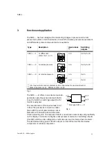
Assignment of the input values In A and In B (see also section 3, Fig.3):
SDE3−...−..Z (1x differential pressure): p1 p2 (measuring pressure
reference pressure): In A (see Fig.3)
SDE3−...−..S (1x relative pressure):
connection p: In A (see Fig.3)
SDE3−...−..D (2 x relative pressure):
connection pA: In A, connection pB: In B
(see Fig.3)
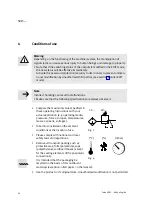
Connect the SDE3−... as follows:
S
Insert the tubing (outer dia.: 4 mm) into the screw connectors. With type
SDE3−...−..D and type SDE3−...−..Z note correct connection.
Electrical installation
Warning
S
Use only power units which guarantee reliable electrical isolation of the
operating voltage as per IEC/DIN EN 60204−1. Observe also the general
requirements for PELV power circuits as per IEC/DIN EN 60204−1.
Note
Long signal cables reduce the immunity to interference.
S
Make sure that the signal cable is not longer than 30 m.
S
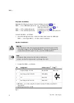
Connect the SDE3−... as follows.
Pin
Assignment
Cable colours
1)
Plug
2)
1
Supply voltage +24 V DC
Brown (BN)
M8, 4−pin
2
Switching output B (Out B)
White (WH)
3
0 V
Blue (BU)
4
Switching output A (out A)
Black (BK)
1)
With SDE3−...−K or when using the connector socket with cable as specified in
Accessories"
2)
Tightening torque max. 0.3 Nm.
Fig.8
Summary of Contents for SDE3 series
Page 27: ...SDE3 Festo SDE3 0604a Deutsch 27 Bild 23 EDIT Modus ...
Page 28: ...SDE3 Festo SDE3 0604a Deutsch 28 Bild 24 TEACH Modus ...
Page 30: ...SDE3 Festo SDE3 0604a Deutsch 30 ...
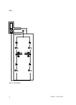
Page 55: ...SDE3 Festo SDE3 0604a English 55 Fig 23 EDIT mode ...
Page 56: ...SDE3 Festo SDE3 0604a English 56 Fig 24 TEACH mode ...


