4
Electrical installation
30
Festo – EXCM-10/-30-...-E-EN – 1612b – English
4.2.4
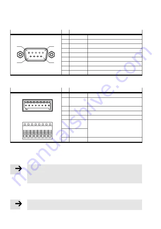
CANopen interface [X3]
Connection
Pin
Function
5
9
6
1
1
–
Not used
2
CAN-L
Low signal
3
0 V (GND)
Reference potential
4
–
Not used
5
Screening
Screened connection
6
–
Not used
7
CAN-H
High signal
8
–
Not used
9
–
Not used
Tab. 4.6
Connection, CANopen interface [X3]
4.2.5
Emergency stop interface [X4]
Connection
Pin
Function
1
8
1
8
Interface at the controller
Plug on connection side
1
+24 V logic
Output: logic v24 V
2
TO
Input: disconnect supply voltage of the
motors (at 0 V)
3
ES
Input: trigger brake edge (at 0 V)
4
RB
Input: release brake (at +24 V)
5
FAULT
Output: malfunction present (at +24 V)
6
DIAG1
(Contact 1)
Potential-free diagnostic contacts.
High impedance with switched-off driver
supply.
(Diagnostic contacts 1 and 2 opened).
7
DIAG2
(Contact 2)
8
0 V (GND)
Reference potential
1)
At rest, the output stage is switched off and any motor brakes present are closed.
2)
The output is high impedance. To signal malfunctions, a low impedance consumer is used.
Tab. 4.7
Connection, emergency stop interface [X4]
The inputs and outputs are designed as PNP. For commissioning of the controller, apply a voltage of
+24 V to the inputs 2 and 3.
Note
If a voltage of +24 V is applied to the RB input (Release brake), the brake is always re
leased and this status can no longer be changed through software. This input serves
mainly to release the brake in order to move planar surface gantries with brake by hand.
4.2.6
Ethernet interface [X5]
The Ethernet interface can thereby be used both for control via the FCT and also for operation via the
function CVE.
Note
Use a network cable of category 5 or better.
Summary of Contents for EXCM-10-***-E
Page 82: ...D Glossary 82 Festo EXCM 10 30 E EN 1612b English...
Page 83: ......


