background image

Product variant

Supported protocol

CMMT­AS­...­EC

EtherCAT

CMMT­AS­...­EP

EtherNet/IP

CMMT­AS­...­PN

PROFINET

Tab. 28 Supported protocol
The physical level of the interface fulfils the requirements according to IEEE 802.3.
The interface is electrically isolated and intended for use with limited cable
lengths 

è

 Tab. 29 Requirements for the connecting cable.

The interface [X19] offers 2 ports.

Port 1, labelled on the device with [X19, XF1 IN]

Port 2, labelled on the device with [X19, XF2 OUT]

2 LEDs are integrated into each of the two RJ45 bushings. The behaviour of the
LEDs depends on the bus protocol. Use is not always made of both LEDs.

Requirements for the connecting cable

Characteristics

CAT 5, patch cable, double shielded

Max. cable length

30 m

Tab. 29 Requirements for the connecting cable

8.9

Motor connection

8.9.1

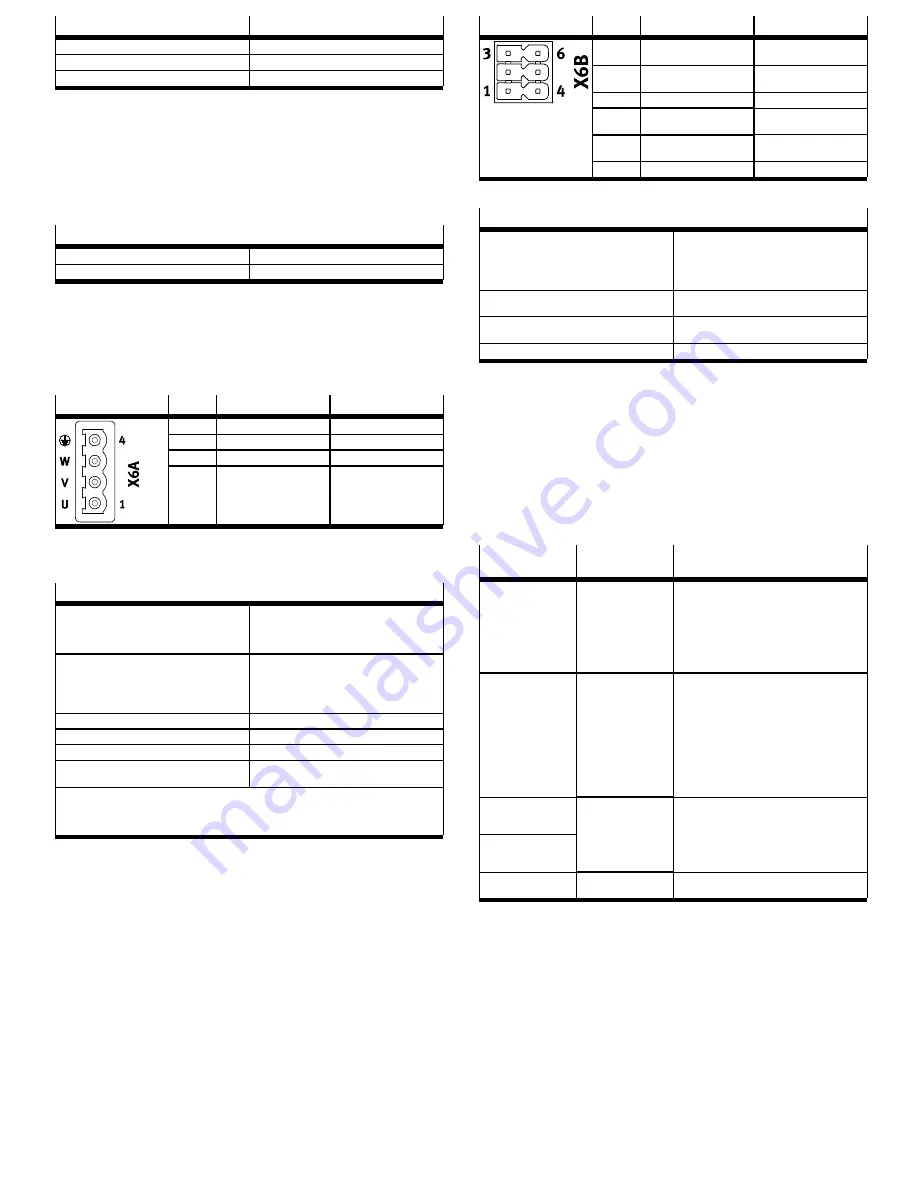
[X6A], Motor phase connection

The connection [X6A] is located on the front of the device. The following connec­
tions to the motor are established via the connection [X6A]:

Motor phases U, V, W

PE connection

[X6A]

Pin

Function

Description

4

PE

Protective earth, motor

3

W

Third motor phase

2

V

Second motor phase

1

U

First motor phase

Tab. 30 Motor phase connection
The cable shield of the motor cable must be placed on the support surface on the
bottom front of the housing and fastened with the shield clamp.

Requirements for the connecting cable

Wires and shielding

4 power wires, shielded

Extra optional cables, e.g. for the holding
brake (shielded separately) and the motor
temperature sensor (shielded separately)

Design

Only use cables that ensure safe separation
between the motor phases and the shielded sig­
nals of the holding brake and motor temperature
sensor.

è

 8.9.4 Shield support of the motor cable

Max. cable length

è

 8.6 Information on EMC­compliant installation

Max. capacitance

<

 250 pF/m

Nominal cross section of power wires

0.75 mm

2

 … 1.5 mm²

Cable diameter of the stripped cable or shield
sleeve (clamping range of the shield clamp)

11 mm … 15 mm

The only motor cables permitted are those that fulfil the requirements of EN 61800­5­2 Annex D.3.1
and the requirements of EN 60204­1.
For cUL, only use Cu cables that have a permissible constant insulation temperature of at least
75 °C.

Tab. 31 Requirements for the connecting cable
Festo offers prefabricated motor cables as accessories

è

 www.festo.com/catalogue.

Only use motor cables that have been approved for operation with the Festo
servo drive. Motor cables of other manufacturers are permitted if they meet
the specified requirements.

8.9.2

[X6B], Motor auxiliary connection

The connection [X6B] is located on the front of the device. The holding brake of
the motor and the motor temperature sensor can be connected to the connection
[X6B]. The output for the holding brake is used both functionally and in connec­
tion with the safety sub­function Safe brake control 

è

 Description Safety sub­

function.
To allow motor temperature monitoring, the following are supported:

N/C and N/O contacts

KTY 81 … 84 (silicon temperature sensors)

PTC (positive temperature coefficient)

NTC (negative temperature coefficient)

Pt1000 (platinum measuring resistor)

The servo drive monitors whether the motor temperature violates an upper or
lower limit. With switching sensors, only the upper limit value can be monitored
(e.g. with a normally closed contact). The limit values and the error reactions can
be parameterised.

[X6B]

Pin

Function

Description

6

MT–

Motor temperature (negat­
ive potential)

5

MT+

Motor temperature (posit­
ive potential)

4

PE

Protective earthing

3

BR–

Holding brake (negative
potential)

2

BR+

Holding brake (positive
potential)

1

PE

Protective earthing

Tab. 32 Motor auxiliary connection

Requirements for the connecting cable

Design

2 wires for the line to the holding brake,
twisted in pairs, separately shielded

2 wires for the line to the temperature
sensor, twisted in pairs, separately shiel­
ded

Min. conductor cross section including cable end
sleeve with plastic sleeve

0.25 mm

2

Max. conductor cross section including cable end
sleeve with plastic sleeve

0.75 mm

2

Max. length

50 m

1)

1) With cable lengths 

>

 25 m, take account of the voltage drop on the cables by selecting appropriate wire

cross sections.

Tab. 33 Requirements for the connecting cable

Requirement for the temperature sensor in the motor

Electrically safe separation from the motor phases in accordance with
IEC 61800­5­1, voltage class C, overvoltage category III.

Shield connection requirements

Make unshielded cable ends as short as possible (max. 150 mm).

Connect the cable shield on both sides.

8.9.3

Electronic overload and overtemperature protection for the motor

The CMMT­AS allows the motor to be electronically protected against overload
and overtemperature by offering the following protective functions:

Protective func-
tions

Description

Measures required during installation
and commissioning

Temperature monitor­
ing of the motor

The motor temperature
is monitored for an
upper and lower limit
value, including hyster­
esis. The limit values
can be parameterised.

Connect temperature sensor to connection
[X6B] (both switching and analogue temper­
ature sensors are supported)

Parameterise temperature limit values in
accordance with type of motor used,
e.g. using the device­specific plug­in.
Respect the permissible limit values of the
motor.

Electronic current limit­
ing and I²t monitoring
of the motor current

The motor current is
monitored electronic­
ally and limited in
accordance with the
limit values specified
by standard

è

 EN 61800­5­1, Tab.

29.
Motor currents and I²t
time constant can be
parameterised.

Parameterise nominal current, maximum
current and I²t time constant of the motor,
e.g. using the device­specific plug­in.

Thermal memory in the
event of motor switch­
off

Thermal memory in the
event of a power sup­
ply failure

Supported, cannot be
parameterised

None

Speed­sensitive over­
load protection

Not supported

Tab. 34 Protective functions for the motor
The specified parameters are preset for Festo motors. The parameters can be
adjusted via the plug­in on parameter page Axis 1/Motor.

8.9.4

Shield support of the motor cable

Requirements for connecting the motor cable shield on the device side

The type of shield connection depends on the design of the motor cable. If,
for example, a hybrid cable is used to connect the motor, holding brake, and tem­
perature sensor, the following options exist for connecting the shield on the
device side:
Option 1: All motor cable shields are jointly connected over a large surface area
using a shield sleeve at the cable end and are connected below the shield clamp
on the front of the CMMT­AS.

Summary of Contents for CMMT-AS-C2-3A-...-S1 Series

Page 1: ...er s address Made in Germany Manufactured in Germany Tab 2 Product labelling example Warning symbols on the front of the product The following warning symbols are located on the front of the product 1 Attention Hot surface 2 Attention General danger point 3 Attention Dangerous voltage 4 5 minutes wait Fig 1 Warning symbols on the front side of the product example CMMT AS EC General meaning Meaning...

Page 2: ...tion SBC is intended to safely hold the motor and axis in posi tion at standstill The safety sub function SS1 is intended for performing a rapid stop with sub sequent torque switch off 2 2 1 Application areas The device is intended for use in an industrial environment Outside of industrial environments measures may need to be implemented for radio interference sup pression e g in commercial and mi...

Page 3: ...tor in the intermediate circuit if and when required Temperature sensors for monitoring the temperature of the power module and of the air in the device Fan in cooling profile depending on product variant The servo drive features a Real time Ethernet interface for process control Vari ous bus protocols are supported depending on the product design EtherCAT Eth erNet IP or PROFINET The device can b...

Page 4: ...thus unavoidable Check whether safety sub func tion SS1 is better suited to your application SBC may only be used for holding brakes or clamping units which engage in the de energised state Ensure the lines are installed in a protected manner SBC request The safety sub function SBC is requested on 2 channels by simultaneously switch ing off the control voltage at both control inputs SBC A and SBC ...

Page 5: ...devices must be placed closer to the mains supply To enable attachment to the rear panel of the control cabinet the servo drive cooling element has a slot on the top in the shape of a keyhole and an ordinary slot on the bottom Assembly of the servo drive WARNING Danger of burns through hot escaping gases and hot surfaces In case of error incorrect wiring or incorrect polarity of the connections X9...

Page 6: ...he CMMT AS has no integrated fuse at the mains input or in the intermediate cir cuit An external fuse is required at the mains supply of the device A device com pound coupled in the intermediate circuit must be protected by means of a com mon mains fuse Different requirements for mains fuses are specified for cUL approval and CE approval Only use line safety switches and fuses that have the releva...

Page 7: ... with the neces sary experience for setting up and commissioning drive systems including their EMC aspects category C2 devices can be used in the first environment residential area When operating category C2 devices limit values apply to the harmonic cur rents in the mains supply EN 61000 3 2 or EN 61000 3 12 Please check whether this is the case for your facility system As a rule compliance with ...

Page 8: ...ring external components channel 0 15 TRG1 Like TRG0 but channel 1 14 CAP0 Fast input for position detection channel 0 13 CAP1 Like CAP0 but channel 1 12 STO A Control input Safe torque off channel A X1A Pin Function Description 11 STO B Control input Safe torque off channel B 10 SBC A Control input Safe brake control channel A 9 SBC B Control input Safe brake control channel B 8 7 6 5 Reserved do...

Page 9: ...nchronised via a device master axis The SYNC inter face can be configured for different functions and can be used as follows Possible functions Description Incremental encoder output Output of a master axis that emulates encoder signals encoder emulation Incremental encoder input Input of a slave axis for receiving the encoder signals of a master axis Pulse direction input Input of a slave axis fo...

Page 10: ... limit With switching sensors only the upper limit value can be monitored e g with a normally closed contact The limit values and the error reactions can be parameterised X6B Pin Function Description 6 MT Motor temperature negat ive potential 5 MT Motor temperature posit ive potential 4 PE Protective earthing 3 BR Holding brake negative potential 2 BR Holding brake positive potential 1 PE Protecti...

Page 11: ... pressure Tab 35 Tightening torque and clamping range 1 Retaining screws of the shield clamp 2 Motor cable 3 Cutout for fastening cable binders 2x 4 Shield clamp 5 Shield of the motor cable is placed over a large area below the shield clamp Fig 12 Shield clamp of the motor cable Connection of the motor cable shield on the motor side Detailed information on the motor side connection with motor cabl...

Page 12: ... connection X1C Connection Pin Type Identifier Function X1A 9 SBC B Safe brake control channel B X1A 10 DIN SBC A Safe brake control channel A X1A X1A 21 DOUT SBA Safe torque off acknowledge X1C 1 BR EXT Output for connection of an external clamping unit high side switch X1C X1C 5 DOUT GND Ground reference potential X6B 1 PE Protective earthing X6B 2 BR Holding brake positive potential X6B X6B 3 O...

Page 13: ...ance free during its period of use and specified service life The test interval varies from one safety sub function to another STO No test has to be carried out during the period of use but we recom mend evaluating STA whenever the sub function is requested to ensure max imum diagnostic coverage and the highest safety related classification SBC Cyclical test required at least once every 24 h and S...

Page 14: ... ISO 13849 1 PL e PL e PL d Probability of dangerous fail ure per hour in accordance with EN 61508 PFH 1 h 3 70 x 10 11 9 40 x 10 11 5 90 x 10 10 Safety reference data for the safety sub function STO Wiring Without high test pulses without or with STA evaluation With high test pulses and with STA evaluation1 With high test pulses and without STA evalu ation Mean time to dangerous fail ure in accor...

Page 15: ...sed electrical operating area in accordance with IEC 61800 5 1 Chap 3 5 Protection class I Overvoltage category III Degree of contamination 2 Vibration resistance in accordance with IEC 61800 5 1 and EN 61800 2 Shock resistance in accord ance with EN 61800 2 Tab 55 Ambient conditions operation Service life Service life of the device with rated load in S1 operation1 and 40 C ambient temperat ure h ...

Page 16: ...S 3 x 0 Input Output voltage with feeding of nominal voltage and nom inal power VRMS 205 Output frequency Hz 0 599 Duration for maximum cur rent fs 5 Hz s 2 Duration for maximum cur rent at standstill fs 5 Hz minimum cycle time 1 s s 0 2 Tab 60 Power specifications motor connection X6A 15 5 Additional technical data Additional technical data on the product and detailed descriptions of all interfac...

Reviews: