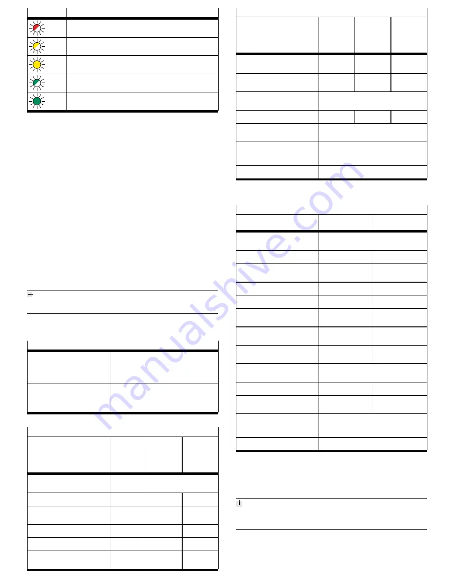
background image

LED

Meaning

Flashes
red

Error in the safety part, or a safety condition has been violated.

Flashes
yellow

The safety sub­function has been requested but is not yet active.

Lights
up yel­
low

The safety sub­function has been requested and is active.

Flashes
green

Output stage, brake outputs and safety diagnostic outputs are blocked (safety
parameterisation is running).

Lights
up
green

Ready, no safety sub­function has been requested.

Tab. 46 Safety LED

12.2

Repair

Repair or maintenance of the product is not permissible. If necessary, replace the
complete product.
1. If there is an internal defect: Always replace the product.
2. Send the defective product unchanged, together with a description of the

error and application, back to Festo.

3. Check with your regional Festo contact person to clarify the conditions for the

return shipment.

13

Dismounting

Disassemble in reverse order of installation.

Before dismounting

1. Switch off the power supply at the master switch.
2. Protect the system from being switched back on accidentally.
3. Wait at least 5 minutes until the intermediate circuit has discharged. 
4. Let the device cool off to room temperature.
5. Before touching the power connections [X6A], [X9A], [X9B], check to ensure

they are free of voltage.

6. Disconnect all electrical lines.

To dismount the device

Loosen retaining screws (2x) and remove the device from the attachment sur­
face.

14

Disposal

ENVIRONMENT!

Send the packaging and product for environmentally sound recycling in accord­
ance with the current regulations 

è

 www.festo.com/sp.

15

Technical data

15.1

Technical data, safety equipment

General safety reference data

Request rate in accordance
with EN 61508

High request rate

Reaction time when the
safety sub­function is
requested

[ms]

<

 10 (applies for STO and SBC)

Error reaction time (how long
it takes for the diagnostic
output status to become cor­
rect once the safety sub­func­
tion has been requested)

[ms]

<

 20 (applies for STA and SBA)

Tab. 47 Safety reference data and safety specifications

Safety reference data for the safety sub-function STO

Wiring

Without high
test pulses,
without or
with STA
evaluation

With high
test pulses
and with STA
evaluation

1)

With high
test pulses
and without
STA evalu­
ation

Safety sub­function in
accordance with
EN 61800­5­2

Safe torque off (STO)

Safety integrity level in
accordance with EN 61508

SIL 3

SIL 3

SIL 2

SIL claim limit for a subsys­
tem in accordance with
EN 62061

SIL CL 3

SIL CL 3

SIL CL 2

Category in accordance with
EN ISO 13849­1

Cat. 4

Cat. 4

Cat. 3

Performance level in accord­
ance with EN ISO 13849­1

PL e

PL e

PL d

Probability of dangerous fail­
ure per hour in accordance
with EN 61508, PFH

[1/h]

3.70 x 10

–11

9.40 x 10

–11

5.90 x 10

–10

Safety reference data for the safety sub-function STO

Wiring

Without high
test pulses,
without or
with STA
evaluation

With high
test pulses
and with STA
evaluation

1)

With high
test pulses
and without
STA evalu­
ation

Mean time to dangerous fail­
ure in accordance with
EN ISO 13849­1, MTTF

d

[a]

2400

1960

1960

Average diagnostic coverage
in accordance with
EN ISO 13849­1, DC

AVG

[%]

97

95

75

Operating life (mission time)
in accordance with
EN ISO 13849­1, T

M

[a]

20

Safe failure fraction SFF in
accordance with EN 61508

[%]

99

99

99

Hardware fault tolerance in
accordance with EN 61508,
HFT

1

Common cause factor for
dangerous undetected fail­
ures 

β

 in accordance with

EN 61508

[%]

5

Classification in accordance
with EN 61508

Type A

1) Safety sub­function STO tested and STA diagnostic output monitored by the safety controller at least 1 x

every 24 h.

Tab. 48 Safety reference data for the safety sub­function STO

Safety reference data for the safety sub-function SBC

Wiring

Two brakes

1)

 with

SBA evaluation

2)

One brake

3)

 without

SBA evaluation

Safety sub­function in
accordance with
EN 61800­5­2

Safe brake control (SBC)

Safety integrity level in
accordance with EN 61508

SIL 3

SIL 1

SIL claim limit for a subsys­
tem in accordance with
EN 62061

SIL CL 3

SIL CL 1

Category in accordance with
EN ISO 13849­1

Cat. 3

Cat. 1

Performance level in accord­
ance with EN ISO 13849­1

PL e

PL c

Probability of dangerous fail­
ure per hour in accordance
with EN 61508, PFH

[1/h]

3.00 x 10

–10

9.00 x 10

–8

Mean time to dangerous fail­
ure in accordance with
EN ISO 13849­1, MTTF

d

[a]

1400

950

Average diagnostic coverage
in accordance with
EN ISO 13849­1, DC

AVG

[%]

93

Operating life (mission time)
in accordance with
EN ISO 13849­1, T

M

[a]

20

Safe failure fraction SFF in
accordance with EN 61508

[%]

99

87

Hardware fault tolerance in
accordance with EN 61508,
HFT

1

0

Common cause factor for
dangerous undetected fail­
ures 

β

 in accordance with

EN 61508

[%]

5

Classification in accordance
with EN 61508

Type A

1) One brake connected to BR+/BR− and a second brake connected to BR­EXT; 2­channel wiring and request

via #SBC­A and #SBC­B.

2) Safety sub­function monitored by the safety controller via the SBA diagnostic output at least 1 x every

24 h.

3) Brake connected either to BR+/BR− or to BR­EXT; 1­channel request via the safety controller using #SBC­A

and #SBC­B; both inputs must be bridged externally.

Tab. 49 Safety reference data for the safety sub­function SBC

The technical data for the safety sub­function SS1 must be calculated individually
according to the application. Use the specified safety reference data for STO and
SBC for the calculation.

Summary of Contents for CMMT-AS-C2-3A-...-S1 Series

Page 1: ...er s address Made in Germany Manufactured in Germany Tab 2 Product labelling example Warning symbols on the front of the product The following warning symbols are located on the front of the product 1 Attention Hot surface 2 Attention General danger point 3 Attention Dangerous voltage 4 5 minutes wait Fig 1 Warning symbols on the front side of the product example CMMT AS EC General meaning Meaning...

Page 2: ...tion SBC is intended to safely hold the motor and axis in posi tion at standstill The safety sub function SS1 is intended for performing a rapid stop with sub sequent torque switch off 2 2 1 Application areas The device is intended for use in an industrial environment Outside of industrial environments measures may need to be implemented for radio interference sup pression e g in commercial and mi...

Page 3: ...tor in the intermediate circuit if and when required Temperature sensors for monitoring the temperature of the power module and of the air in the device Fan in cooling profile depending on product variant The servo drive features a Real time Ethernet interface for process control Vari ous bus protocols are supported depending on the product design EtherCAT Eth erNet IP or PROFINET The device can b...

Page 4: ...thus unavoidable Check whether safety sub func tion SS1 is better suited to your application SBC may only be used for holding brakes or clamping units which engage in the de energised state Ensure the lines are installed in a protected manner SBC request The safety sub function SBC is requested on 2 channels by simultaneously switch ing off the control voltage at both control inputs SBC A and SBC ...

Page 5: ...devices must be placed closer to the mains supply To enable attachment to the rear panel of the control cabinet the servo drive cooling element has a slot on the top in the shape of a keyhole and an ordinary slot on the bottom Assembly of the servo drive WARNING Danger of burns through hot escaping gases and hot surfaces In case of error incorrect wiring or incorrect polarity of the connections X9...

Page 6: ...he CMMT AS has no integrated fuse at the mains input or in the intermediate cir cuit An external fuse is required at the mains supply of the device A device com pound coupled in the intermediate circuit must be protected by means of a com mon mains fuse Different requirements for mains fuses are specified for cUL approval and CE approval Only use line safety switches and fuses that have the releva...

Page 7: ... with the neces sary experience for setting up and commissioning drive systems including their EMC aspects category C2 devices can be used in the first environment residential area When operating category C2 devices limit values apply to the harmonic cur rents in the mains supply EN 61000 3 2 or EN 61000 3 12 Please check whether this is the case for your facility system As a rule compliance with ...

Page 8: ...ring external components channel 0 15 TRG1 Like TRG0 but channel 1 14 CAP0 Fast input for position detection channel 0 13 CAP1 Like CAP0 but channel 1 12 STO A Control input Safe torque off channel A X1A Pin Function Description 11 STO B Control input Safe torque off channel B 10 SBC A Control input Safe brake control channel A 9 SBC B Control input Safe brake control channel B 8 7 6 5 Reserved do...

Page 9: ...nchronised via a device master axis The SYNC inter face can be configured for different functions and can be used as follows Possible functions Description Incremental encoder output Output of a master axis that emulates encoder signals encoder emulation Incremental encoder input Input of a slave axis for receiving the encoder signals of a master axis Pulse direction input Input of a slave axis fo...

Page 10: ... limit With switching sensors only the upper limit value can be monitored e g with a normally closed contact The limit values and the error reactions can be parameterised X6B Pin Function Description 6 MT Motor temperature negat ive potential 5 MT Motor temperature posit ive potential 4 PE Protective earthing 3 BR Holding brake negative potential 2 BR Holding brake positive potential 1 PE Protecti...

Page 11: ... pressure Tab 35 Tightening torque and clamping range 1 Retaining screws of the shield clamp 2 Motor cable 3 Cutout for fastening cable binders 2x 4 Shield clamp 5 Shield of the motor cable is placed over a large area below the shield clamp Fig 12 Shield clamp of the motor cable Connection of the motor cable shield on the motor side Detailed information on the motor side connection with motor cabl...

Page 12: ... connection X1C Connection Pin Type Identifier Function X1A 9 SBC B Safe brake control channel B X1A 10 DIN SBC A Safe brake control channel A X1A X1A 21 DOUT SBA Safe torque off acknowledge X1C 1 BR EXT Output for connection of an external clamping unit high side switch X1C X1C 5 DOUT GND Ground reference potential X6B 1 PE Protective earthing X6B 2 BR Holding brake positive potential X6B X6B 3 O...

Page 13: ...ance free during its period of use and specified service life The test interval varies from one safety sub function to another STO No test has to be carried out during the period of use but we recom mend evaluating STA whenever the sub function is requested to ensure max imum diagnostic coverage and the highest safety related classification SBC Cyclical test required at least once every 24 h and S...

Page 14: ... ISO 13849 1 PL e PL e PL d Probability of dangerous fail ure per hour in accordance with EN 61508 PFH 1 h 3 70 x 10 11 9 40 x 10 11 5 90 x 10 10 Safety reference data for the safety sub function STO Wiring Without high test pulses without or with STA evaluation With high test pulses and with STA evaluation1 With high test pulses and without STA evalu ation Mean time to dangerous fail ure in accor...

Page 15: ...sed electrical operating area in accordance with IEC 61800 5 1 Chap 3 5 Protection class I Overvoltage category III Degree of contamination 2 Vibration resistance in accordance with IEC 61800 5 1 and EN 61800 2 Shock resistance in accord ance with EN 61800 2 Tab 55 Ambient conditions operation Service life Service life of the device with rated load in S1 operation1 and 40 C ambient temperat ure h ...

Page 16: ...S 3 x 0 Input Output voltage with feeding of nominal voltage and nom inal power VRMS 205 Output frequency Hz 0 599 Duration for maximum cur rent fs 5 Hz s 2 Duration for maximum cur rent at standstill fs 5 Hz minimum cycle time 1 s s 0 2 Tab 60 Power specifications motor connection X6A 15 5 Additional technical data Additional technical data on the product and detailed descriptions of all interfac...

Reviews: