


7. Electrical installation
70
Festo P.BE-CMMP-AS-3A-HW-EN 0708NH
The intermediate circuits of several CMMP-AS servo positioning controllers can be con-
nected via the ZK+ and ZK- terminals. Coupling of the intermediate circuits is useful in
applications where high braking energies occur or where motion must still be performed
when the power supply fails (see A3).
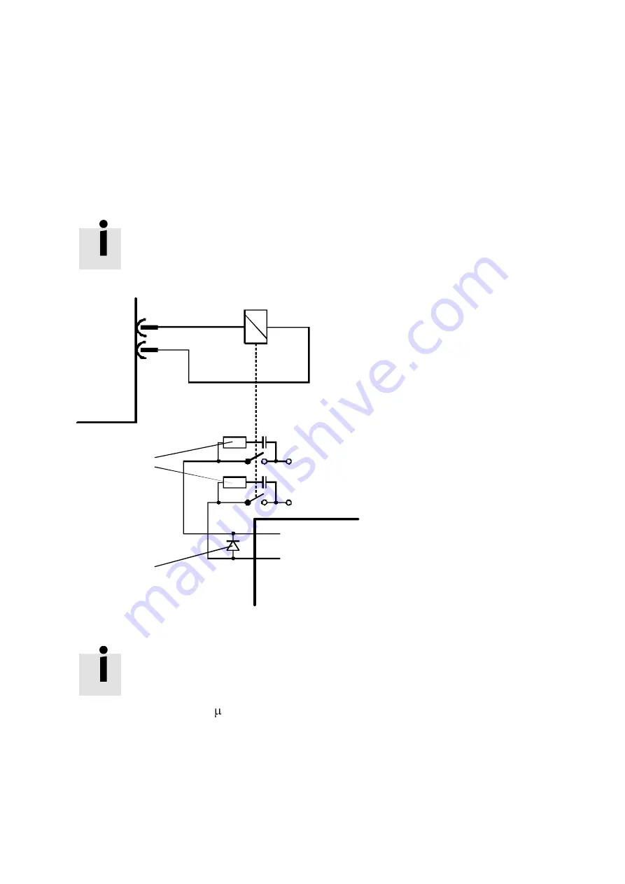
A motor holding brake can be connected to terminals BR+ and BR-. The locking brake is fed
from the servo positioning controller power supply. The maximum output current provided
by the CMMP-AS servo positioning controller must be noted. It may be necessary to insert
a relay between the device and the locking brake, as shown in fig 7.4
To release the holding brake, the voltage tolerances at the holding
brake connection terminals must be maintained.
Observe the specifications in table A8 for this.
Br+
Br-
ARS 2100
Motor
+24 V power supply
GND power supply
+24 V brake
GND brake
free-wheeling diode
Resistor and
capacitor for
spark extinguishing
CMMP-AS
Fig. 7.3 Connecting a high-current (> 1 A) lockable brake to the device
Switching inductive DC currents via relays cause heavy currents
and sparks. For interference suppression, we recommend inte-
grated RC interference suppressors, e.g. from Evox RIFA, part num-
ber: PMR205AC6470M022 (RC suppressor with 22Ω in series with
0.47 F).
7.5
Connection: I/O communication [X1]
Fig. 7.4 shows the main functions of the digital and analogue inputs and outputs. The
CMMP-AS servo positioning controller is shown to the right and the controlled connections
to the left. The cable layout can also be seen.
Summary of Contents for CMMP-AS-C2-3A
Page 2: ......