CESA-GW-AS-PB Description
59
7.1.3
I/O Data
7.1.3.1
Process data
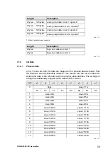
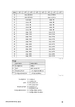
In V2.1 mode the AS-i I/O data are mapped in the process data as known from
the Siemens and AS-i/InterBus masters. This means that the lower nibble de-
scribes the data of the AS-i slave with the higher slave address. The ec-flags or
hi-flags are additionally mapped at the nibble of AS-i slave 0.
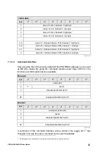
Length
description
2 bytes … 128 bytes
analog input data circuit 1, dynamic
1
1. Module parameters necessarily
2 bytes … 128 bytes
analog output data circuit 1, dynamic
1
2 bytes … 128 bytes
analog input data circuit 2, dynamic
1
2 bytes … 128 bytes
analog output data circuit 2, dynamic
1
Tab. 7-13.
Length
description
2 bytes
flags and detector circuit 1
2 bytes
flags and detector circuit 2
Tab. 7-14.
byte
2
7
2
6
2
5
2
4
2
3
2
2
2
1
2
0
0
flags
slave 1/1A
F3
F2
F1
F0
D3
D2
D1
D0
1
slave 2/2A
slave 3/3A
2
slave 4/4A
slave 5/5A
3
slave 6/6A
slave 7/7A
4
slave 8/8A
slave 9/9A
5
slave 10/10A
slave 11/11A
6
slave 12/12A
slave 13/13A
7
slave 14/14A
slave 15/15A
8
slave 16/16A
slave 17/17A
9
slave 18/18A
slave 19/19A
10
slave 20/20A
slave 21/21A
11
slave 22/22A
slave 23/23A
12
slave 24/24A
slave 25/25A
13
slave 26/26A
slave 27/27A
Tab. 7-15.
Summary of Contents for CESA-GW-AS-PB
Page 1: ...Description AS i Gateway English Gateway AS i PROFIBUS CESA GW AS PB 749962 1002NH ...
Page 2: ......
Page 4: ......

