background image

OBID i-scan

®

System-Manual

ID ISC.LR200

FEIG ELECTRONIC GmbH

Page 165 of 174

H90692-16e-ID-B.doc

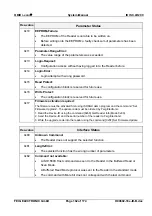
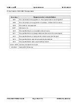
Error-Code for ISO15693 Transponders


Hex-value


Response error code definition


0x01

The command is not supported, i.e. the request code is not recognized


0x02

The command is not recognized, for example: a format error occurred


0x03


The option is not supported


0x0F


Unknown error


0x10


The specified block is not available (doesn’t exist)


0x11


The specified block is already locked and thus cannot be locked again


0x12


The specified block is locked and its content cannot be changed


0x13


The specified block was not successfully programmed


0x14


The specified block was not successfully locked


0xA0 - 0xDF


Custom command error codes


all others


reserved for future use

Summary of Contents for OBID i-scan ID ISC.LR200 Series

Page 1: ...MANUAL final public B 2006 12 22 H90692 16e ID B doc OBID i scan ID ISC LR200 Standard Reader Firmware Version 5 04 and higher...

Page 2: ...e completely avoided we are always grateful for your useful tips The installation instructions given in this manual are based on advantageous boundary conditions FEIG ELECTRONIC GmbH does not give any...

Page 3: ...nds 14 2 3 Buffered Read Mode 17 2 4 Scan Mode 18 2 5 Reader Multiplex Mode 20 2 6 Asynchronous Interface 21 2 6 1 Data Format and Protocol Frames 21 2 6 2 CRC16 Calculation Algorithm 22 3 Configurati...

Page 4: ...Protocols for Reader Configuration 62 4 1 0xA0 Reader Login 62 4 2 0x80 Read Configuration 63 4 3 0x81 Write Configuration 64 4 4 0x82 Save Configuration to EEPROM 65 4 5 0x83 Set Default Configuratio...

Page 5: ...s for ISO15693 Mandatory and Optional Commands 85 7 1 1 0x01 Inventory 86 7 1 2 0x02 Stay Quiet 88 7 1 3 0x22 Lock Multiple Blocks 89 7 1 4 0x23 Read Multiple Blocks 90 7 1 5 0x24 Write Multiple Block...

Page 6: ...Inventory Read 121 7 2 5 ST Microelectronics Custom Commands 123 7 2 5 1 0xA0 Activate EAS 123 7 2 5 2 0xA1 Deactivate EAS 124 7 3 0xBF ISO15693 Transparent Command 125 7 4 Supported ISO15693 Host com...

Page 7: ...uffered Read Mode Procedure 149 8 2 Transponder Access in the Buffered Read Mode 150 8 3 0x21 Read Buffer 151 8 4 0x31 Read Data Buffer Info 153 8 5 0x32 Clear Data Buffer 154 8 6 0x33 Initialize Buff...

Page 8: ...6e ID B doc ISO Host Command DB Size of the transponder 4 bytes 171 Buffered Read Mode BRM DB Size of the transponder 4 bytes 172 ISO Host Command DB Size of the transponder 8 bytes 172 Buffered Read...

Page 9: ...arameter 55 Magnetic Strip Emulation 12e 17 10 02 56 Wiegand Emulation 49 Reader Multiplex Mode is also available in Scan Mode 49 Default values in CFG12 DB Adr and has been changed 45 Default values...

Page 10: ...parameter 36 CFG8 New parameter ISO Blocksize 42 151 CFG10 New parameter ANT Store for ID ISC MUX 130 Fujitsu mb98r116 ISO15693 commands 71 New Protocol 0x66 Get Reader Info 42 CFG10 New parameter Al...

Page 11: ...ic FIFO First in First out frq Frequency FSK Frequency Shift Keying h Hour Hz Hertz ID Identification IN Input LEN Length LOC Location LSB Least Significant Byte min Minutes ms Milliseconds MSB Most S...

Page 12: ...itable for mounting on for example conveyors A mixed function of different OBID i scan Reader types within the same installation is possible by means of a uniform communication interface Each Reader i...

Page 13: ...chronous interface RS232 RS485 Configuration Commands Reader Control Commands ISO15693 Host Commands Buffered Read Mode Scan Mode 2 1 Configuration Commands Control Commands This method of data transm...

Page 14: ...riting data in addressed mode the UID of the Transponder has to be known This is executed by sending the protocol 7 1 1 0x01 Inventory If a Transponder is located within the detection range of the Rea...

Page 15: ...if only one Transponder is located within the range of the Reader The following chart will show the necessary steps for the communication with a Transponder in non addressed mode Host Terminal PC Read...

Page 16: ...st include its UID The following chart will show the necessary steps for the communication with a Transponder in selected mode Host Terminal PC Reader Inventory to get the UID Transponder in antenna f...

Page 17: ...ad Buffer command This command always reads the first available data sets from the data buffer However already read data has to be deleted with the 8 5 0x32 Clear Data Buffer command before the next d...

Page 18: ...Transponder will not send out Scan Mode via asynchronous interface The data will be sent out depending on their configuration according to the following scheme the sequence of which cannot be changed...

Page 19: ...cols shall be sent to the Reader while the Scan Mode is active no Transponder should be within the detection range of the Reader during this time Only read operations are available with the Scan Mode...

Page 20: ...Buffered Read Mode must be enabled in the 3 10 CFG10 General System Parameters configuration block and the Multiplex Mode must be selected in the SYNC setting in the 3 11 CFG11 Buffered Read Mode conf...

Page 21: ...from the Reader if there is a protocol frame failure Protocol frame Host Reader 1 2 3 4 n 2 n 1 n LENGTH n COM ADR CONTROL BYTE PROTOCOL DATA LSB CRC16 MSB CRC16 Host Reader 1 2 3 4 5 n 2 n 1 n LENGT...

Page 22: ...r Reaction time Starting delay 5 n ms min 5 ms Host Reader Data timeout Within one protocol the characters have to follow each other in intervals of maximum 12 ms max 12 ms max 12 ms max 12 ms Host Re...

Page 23: ...fies the location of the configuration block RAM EEPROM MODE specifies one or all configuration blocks Bit 7 6 5 4 3 2 1 0 Function LOC MODE CFGn address of configuration block The EEPROM configuratio...

Page 24: ...after writing saving this configuration block into EEPROM and a Reader reset not marked Changing of this parameter becomes immediately effective after writing saving this configuration block to RAM m...

Page 25: ...st logs into the Reader for a read write access to the configuration parameter blocks Notes A READER ID 0x00000000 disables the password function A read with the command 4 2 0x80 Read Configuration wi...

Page 26: ...0x00 0x00 0x00 IDLE MODE Defines the status of the signal emitters OUT1 OUT2 and REL during the idle mode Bit 15 14 13 12 11 10 9 8 Function REL mode OUT2 mode OUT1 mode 0 0 7 6 5 4 3 2 1 0 0 0 0 0 0...

Page 27: ...00ms 0s 6553 5s OUT2 TIME Defines the holding time of the digital output OUT2 If the Reader receives a valid Transponder response the Output2 is activated for the value in OUT2 TIME If OUT2 TIME is ze...

Page 28: ...if data clock Interface is enabled 4 red 1 The RF interface re reads Tag it HF or ISO15693 Transponders in Buffered Read or Scan Mode 2 Data if data clock Interface is enabled 5 red 1 The Reader is i...

Page 29: ...ications with the RS485 interface Notes Do not configure address 255 Via the COM Adr 255 in the send protocol the Reader is able to be addressed at any time It answers then with the configured address...

Page 30: ...s b0 8 data bits b1 do not use S Number of stop bits b0 1 stop bit b1 do not use Note Changing of TRANS FORM only becomes effective after writing saving configuration block CFG1 to EEPROM and reset of...

Page 31: ...ill send an answer protocol In this case the current commands between Reader and Transponder are aborted If this time is too short the Interface Status 0x83 RF Communication Error will appear max resp...

Page 32: ...available with ID ISC M02 ID ISC MR PR101 D Driver for ISO15693 G Driver for I Code EPC must be released first H Driver for I Code UID must be released In principle only those Transponder drivers shou...

Page 33: ...eader answers every command with the error code 0x84 Changing of RF POWER only becomes effective after writing saving configuration block CFG3 to EEPROM and a reset of the Reader EAS LEVEL only I Code...

Page 34: ...tomatically 0x01 noise level is set with the parameters set in NOISE MIN NOISE AVG NOISE MAX or with the command 5 8 0x6C Set Noise Level Notes In the NL MODE b0 the Reader continuously measures the n...

Page 35: ...ection Mask only I Code EPC Transponder The I Code EPC Transponder supports a selection feature in which groups of Transponders may be selected The parameters in these configuration blocks define the...

Page 36: ...Bits 1 2 3 4 5 6 7 8 9 10 11 12 13 14 15 16 17 18 19 20 Selection Mask 0 0 0 0 0 0 0 1 0 0 0 0 0 0 1 0 0 0 0 0 0x01 0x02 Only Transponders whose serial numbers begin with 0000 0001 00 return an answer...

Page 37: ...b1 Original I Code Memory Model FAM CODE only I Code 1 Transponders Family Code to select a Transponder APP ID only I Code 1 Transponders Application ID to select a Transponder Note If FAM CODE and AP...

Page 38: ...0 SUB CARRIER b0 ASK one sub carrier b1 FSK two sub carriers Note In FSK Mode the number of timeslots NO TS should be 16 but if only one Transponder is in the field the number of timeslots may be set...

Page 39: ...details about the correct WR OPTION ISO CMD OPTION only ISO15693 Transponder driver Bit 7 6 5 4 3 2 1 0 Function 0 0 0 0 0 0 BREAK BREAK b10 break timeslot at NO Transponder Break is always 100 modula...

Page 40: ...O TAGIT OPTION must be disabled ISO Blocksize Bit 7 6 5 4 3 2 1 0 Function Read Mode Blocksize DB Blocksize DB Blocksize Defines the block size of an ISO transponder which is not listed in the MFR tab...

Page 41: ...bH Page 41 of 174 H90692 16e ID B doc 3 9 CFG9 Reserved The configuration block CFG9 is reserved for future use Byte 0 1 2 3 4 5 6 Contents 0x00 0x00 0x00 0x00 0x00 0x00 0x00 Default Byte 7 8 9 10 11...

Page 42: ...Mode b00 ISO Host Mode b01 Buffered Read Mode b10 Scanner Mode ISO Host Mode This bit combination activates the ISO15693 Host Mode If the ISO15693 Host Mode is enabled the ISO15693 Host commands will...

Page 43: ...1 0 Function ANT STORE ALARM MODE NO RF RESET NO RF RESET If this bit is not set the reader switches off the RF field for 10ms if no transponder sends an response after 5 inventory commands ALARM MOD...

Page 44: ...STORE 0 Tag was detected by antenna 2 and 5 two data sets data set 1 antenna number 0x02 data set 2 antenna number 0x10 Note If ANT STORE 1 and Tag was detected by antenna 1 and data set was transmit...

Page 45: ...eral Transponder Parameters Byte 0 1 2 3 4 5 6 Contents TR DATA 7 DB ADR 1 DB N 1 2 TR ID 1 2 VALID TIME 1 READ 1 Default 0x01 0x05 0x01 0x85 0x00 0x0A 0x00 Byte 7 8 9 10 11 12 13 Contents SYNC SYNC T...

Page 46: ...ported ISO15693 Host commands for ISO15693 Transponders DB N 8 Number of data blocks Range 0x01 0x20 The data block size in the Buffered Read Mode is always 4 bytes see Annex Buffered Read Mode BRM DB...

Page 47: ...period of time during which a Transponder cannot be read a 2nd time Note Changing of VALID TIME only becomes effective after writing saving configuration block CFG11 to EEPROM and reset of the Reader...

Page 48: ...er has completed its task of RF Communication and passes the control to the next Reader the RF field will not be switched off only the task will stopped b1 After the Reader has completed its task of R...

Page 49: ...SCAN DATA DB ADR D LGT SCAN LOCK TIME Default 0x02 0x00 0x01 0x05 0x04 0x00 Byte 7 8 9 10 11 12 13 Contents SCAN LOCK TIME D START DB USE SEP CHAR SEP USR END CHAR END USR Default 0x0A 0x00 0x02 0x20...

Page 50: ...ock cannot be enabled at the same time DC FORMAT By means of this parameter the kind of data transmission via data clock interface could by selected b000 Wiegand emulation see 3 12 2 Wiegand Emulation...

Page 51: ...the antenna number will be always 1 The number of the antenna will The antenna number will only be transferred via asynchronous interface not via data clock interface TIME b0 Output of internal system...

Page 52: ...or outside of it DB ADR Transponder address of the first data block which will be transferred in Scan Mode Range 0x00 0xFF See for valid addresses ANNEX G Memory Model I Code 1 Transponders and 7 4 S...

Page 53: ...Function 0 0 0 0 DB FORMAT DB FORMAT b0000 unformatted hex data In this case the data are transferred as they were read by the Transponder b0010 ASCII formatted hex data In this case the raw data fro...

Page 54: ...x00 USER user defined in SEP USR Note Only one option could be selected SEP USR User defined separation character END CHAR selects the end character between two data types for the send data Bit 7 6 5...

Page 55: ...0 0 0x5 b 0 1 0 1 b 1 0 1 0 1 b 0 0 1 0 1 0 1 0x6 b 0 1 1 0 b 1 0 1 1 0 b 0 0 1 0 1 1 0 0x7 b 0 1 1 1 b 0 0 1 1 1 b 1 0 1 0 1 1 1 0x8 b 1 0 0 0 b 0 1 0 0 0 b1 0 1 1 0 0 0 0x9 b 1 0 0 1 b 1 1 0 0 1 b...

Page 56: ...tn 3 tb n tn 2 tv ts 10 12 ms 3 12 2 Wiegand Emulation Data Format The output data format in Wiegand emulation is equal like the data coding on the Transponder For cutting the length of data output th...

Page 57: ...of timeslots MIN TS MAX TS Number of Timeslots b111 b110 b101 b100 b011 b010 b001 b000 256 128 64 32 16 8 4 1 Each I Code 1 and I Code EPC Transponder responds in a chosen timeslot Choosing too few ti...

Page 58: ...p a fixed hash value both MIN HASH and MAX HASH must contain the value of the desired hash value and DIFF HASH is ignored hash values MIN HASH MAX HASH DIFF HASH 0 0 0 ignored 0 4 8 0 8 4 0 4 8 2 6 10...

Page 59: ...ransponders in the field will be send to the host The Reader performs an RF Reset before any command reads a Serial Number b1 only the new selected Transponders will be sent to the host 3 14 CFG14 Res...

Page 60: ...0 0x00 0x00 Default MUX MODE Activates or deactivates multiplexing and determines when the next output is selected Bit 7 6 5 4 3 2 1 0 Function 0 0 0 0 0 0 MUX Switch Condition Multiplexing Mutiplexin...

Page 61: ...per input can be active at a time In Single Mode only one channel is enabled whereas in Dual Mode two channels are enabled OUTPUT CHANNELS Specifies the number of the used output channels The allocat...

Page 62: ...cess locking for the configuration parameters stored in the EEPROM of the Reader 4 1 0xA0 Reader Login The Reader Login must be executed after every power up or 5 3 0x63 CPU Reset command if an access...

Page 63: ...0 STATUS 10 CFG REC CRC16 CFG ADR 11 Bit 7 6 5 4 3 2 1 0 Function LOC 0 CFGn Address of Configuration Block CFGn memory address of the required configuration block LOC specifies the location of the co...

Page 64: ...EC CRC16 Host Reader 1 2 3 4 5 6 6 COM ADR 0x81 STATUS 12 CRC16 CFG ADR 13 Bit 7 6 5 4 3 2 1 0 Function LOC 0 CFGn Address of Configuration Block CFGn memory address of the required configuration bloc...

Page 65: ...nfiguration Block CFGn memory address of the required configuration block MODE specifies one or all configuration blocks b0 configuration block specified by CFGn b1 all configuration blocks Notes The...

Page 66: ...or all configuration blocks b0 configuration block specified by CFGn b1 all configuration blocks LOC specifies the location of the configuration block b0 RAM b1 RAM and EEPROM Notes The configuration...

Page 67: ...6 6 COM ADR 0x85 STATUS 18 CRC16 TIMER Byte 4 5 6 7 TIME h min ms 0 23 0 59 0 59999 Note The internal system timer is not a real time clock RTC and the accuracy cannot be guaranteed 4 7 0x86 Get Syste...

Page 68: ...protocol starts the Flash Loader inside the Reader Use the Windows program MEMTOOL to process the firmware update Please refer Application Note Firmware Update ID ISCLR200 for details Host Reader 1 2...

Page 69: ...he firmware Byte 5 6 Bit 7 4 3 0 7 0 Function decoder firmware main controller firmware D REV Revision status of the development firmware D REV is set to 0 in customized firmware revisions HW TYPE Typ...

Page 70: ...0 of 174 H90692 16e ID B doc SW TYPE Type of Reader firmware 0x28 ID ISC LR100 40 0x29 ID ISC LR200 41 TR TYPE Displays the Transponders supported by the software Bit 15 14 13 12 11 10 9 8 Function Bi...

Page 71: ...17 COM ADR 0x66 STATUS 21 SW REV D REV 8 9 10 11 12 13 14 15 16 17 HW TYPE SW TYPE TR TYPE RX BUF TX BUF CRC16 Host Reader Mode 0x80 Device_ID 1 2 3 4 5 8 9 12 22 COM ADR 0x66 STATUS 22 DEV_ID Custom_...

Page 72: ...PROTOCOL LENGTH ERROR TX BUF TX BUF is the maximum transmit buffer size of the Reader The host has to take in to account that a response protocol of the Reader can have this length DEV_ID Individual d...

Page 73: ...ase setting Host Reader 1 2 3 4 5 5 COM ADR 0x69 CRC16 Host Reader 1 2 3 4 5 6 6 COM ADR 0x69 STATUS 23 CRC16 Notes After an RF Reset the Reader is not able to receive a new Transponder before expirat...

Page 74: ...ld of the Reader antenna ON and OFF Host Reader 1 2 3 4 5 6 6 COM ADR 0x6A RF CRC16 Host Reader 1 2 3 4 5 6 6 COM ADR 0x6A STATUS 1 CRC16 RF 0x00 RF Field of Reader antenna is OFF 0x01 RF Field of Rea...

Page 75: ...x NL Value min NL avg NL and max NL in mV Note To make the new noise levels permanent the 3 5 CFG4 RF Interface II configuration block has to be saved to non volatile memory with the command 4 4 0x82...

Page 76: ...2 3 4 5 6 6 COM ADR 0x6E MODE CRC16 Host Reader 1 2 3 4 5 n 2 n 1 n n COM ADR 0x6E STATUS DATA CRC16 MODE Reader Diagnostic Modes 0x01 Listing of detail information for STATUS 0x84 DATA Response for R...

Page 77: ...emp alarm level OFF ON Note These error conditions are effective beginning with hardware version FE498 3 and 4 Jumper J2 must be in Error Conditions 2nd Byte Error Set condition Clear condition RF Pow...

Page 78: ...for tuning the complementary antenna The output power is set to about 4 watt without any readjust If the Reader is in the buffered read mode it will be switched off and communication with Transponders...

Page 79: ...e protocol if they are 0 Host Reader 1 2 3 4 5 6 7 13 COM ADR 0x71 OS OSF 8 9 10 11 12 13 0x00 OUT TIME CRC16 Host Reader 1 2 3 4 5 6 6 COM ADR 0x71 STATUS 26 CRC16 OS The word OS Output State defines...

Page 80: ...1 1 Hz b10 2 Hz b01 4 Hz b00 8 Hz OUT TIME By the values defined by OUT TIME the outputs OUT1 OUT2 REL can be activated temporary or unlimited perid Exceptions are the time values 0 and 65535 0xFFFF s...

Page 81: ...this protocol the actual status of the digital inputs IN1 IN2 and DIP1 DIP4 can be queried at any time Host Reader 1 2 3 4 5 5 COM ADR 0x74 CRC16 Host Reader 1 2 3 4 5 6 7 7 COM ADR 0x74 STATUS 27 INP...

Page 82: ...6 6 COM ADR 0x1B STATUS 30 CRC16 6 2 0x1C EAS only I Code 1 Transponders This command sends an EAS request to the Transponder If the EAS function of the Transponder is active the Transponder answers...

Page 83: ...0 I Code EPC b001 I Code UID EPC 12 Byte I Code EPC Data electronic product code If the I Code EPC data has only a length of 8 Byte the I Code EPC must be written left justified Byte 5 12 The last 4 B...

Page 84: ...model see ANNEX G Memory Model I Code 1 Transponders The following combinations are possible Transponder Types I Code 1 Tag it HF ISO I Code EPC Host commands for ISO15693 Mandatory and Optional Comma...

Page 85: ...onder Host Reader 1 2 3 4 n 2 n 1 n n COM ADR 0xB0 REQUEST DATA CRC16 Host Reader 1 2 3 4 5 n 2 n 1 n n COM ADR 0xB0 STATUS 31 RESPONSE DATA CRC16 REQUEST DATA Command specific request RESPONSE DATA C...

Page 86: ...the 3 13 CFG13 Anticollision configuration block is not set if anticollision is OFF 3 10 CFG10 General System Parameters REQUEST DATA 4 5 0x01 MODE RESPONSE DATA 5 6 7 8 15 DATA SETS TR TYPE DSFID UID...

Page 87: ...f the STATUS byte of the protocol frame has the value 0x94 more Serial Numbers can be read out of the Reader with MORE b1 Using I Code EPC and only under condition that min max Timeslots 1 CFG13 Antic...

Page 88: ...Quiet This command sets one Transponder to Quiet State Only needed if anticollision is switched OFF REQUEST DATA 4 5 6 13 0x02 MODE UID MODE Bit 7 6 5 4 3 2 1 0 Function 0 0 0 0 0 ADR ADR b001 address...

Page 89: ...DATA STATUS 0x03 5 DB ADR E RESPONSE DATA STATUS 0x95 5 6 ISO ERROR DB ADR E MODE Bit 7 6 5 4 3 2 1 0 Function 0 0 0 0 0 ADR ADR b000 non addressed b001 addressed b010 selected UID Read only serial n...

Page 90: ...DB SIZE SEC STATUS DB Repeated DB N times MODE Bit 7 6 5 4 3 2 1 0 Function 0 0 0 0 SEC ADR ADR b000 non addressed b001 addressed b010 selected SEC b0 SEC STATUS always 0x00 b1 security status of fol...

Page 91: ...es a Read Single Block command to the Transponder If a Transponder does not support Read Multiple Blocks commands several Read Single Block commands are used for this Transponder Only one Transponder...

Page 92: ...ERROR DB ADR E MODE Bit 7 6 5 4 3 2 1 0 Function 0 0 0 0 0 ADR ADR b000 non addressed b001 addressed b010 selected UID Read only serial number of the Transponder The UID is required only in the addres...

Page 93: ...e Single Block command to the Transponder This will be managed by the Reader internally If a Transponder does not support Write Multiple Blocks commands several Write Single Block commands are used fo...

Page 94: ...An already selected Transponder will automatically be set to Ready State REQUEST DATA 4 5 6 13 0x25 MODE UID RESPONSE DATA STATUS 0x95 5 ISO ERROR MODE Bit 7 6 5 4 3 2 1 0 Function 0 0 0 0 0 ADR ADR...

Page 95: ...ODE UID RESPONSE DATA STATUS 0x95 5 ISO ERROR MODE Bit 7 6 5 4 3 2 1 0 Function 0 0 0 0 0 ADR ADR b000 non addressed b001 addressed b010 selected UID Read only serial number of the Transponder The UID...

Page 96: ...commands for ISO15693 Transponders REQUEST DATA 4 5 6 13 6 14 0x27 MODE UID AFI RESPONSE DATA STATUS 0x95 5 ISO ERROR MODE Bit 7 6 5 4 3 2 1 0 Function 0 0 0 0 0 ADR ADR b000 non addressed b001 addre...

Page 97: ...ter 7 4 Supported ISO15693 Host commands for ISO15693 Transponders REQUEST DATA 4 5 6 13 0x28 MODE UID RESPONSE DATA STATUS 0x95 5 ISO ERROR MODE Bit 7 6 5 4 3 2 1 0 Function 0 0 0 0 0 ADR ADR b000 no...

Page 98: ...mmands for ISO15693 Transponders REQUEST DATA 4 5 6 13 6 14 0x29 MODE UID DSFID RESPONSE DATA STATUS 0x95 5 ISO ERROR MODE Bit 7 6 5 4 3 2 1 0 Function 0 0 0 0 0 ADR ADR b000 non addressed b001 addres...

Page 99: ...hapter 7 4 Supported ISO15693 Host commands for ISO15693 Transponders REQUEST DATA 4 5 6 13 0x2A MODE UID RESPONSE DATA STATUS 0x95 5 ISO ERROR MODE Bit 7 6 5 4 3 2 1 0 Function 0 0 0 0 0 ADR ADR b000...

Page 100: ...it HF MODE Bit 7 6 5 4 3 2 1 0 Function 0 0 0 0 0 ADR ADR b000 non addressed b001 addressed b010 selected UID Read only serial number of the Transponder The UID is required only in the addressed mode...

Page 101: ...he Transponder this value will return 0x0000 Byte 15 16 Bit 7 5 4 0 7 0 content res Block size in Bytes 1 Number of blocks 1 IC REF IC reference version of the Transponder If not supported by the Tran...

Page 102: ...n addressed b001 addressed b010 selected UID Read only serial number of the Transponder The UID is required only in the addressed mode DB ADR First block number from which security status is requested...

Page 103: ...ory model see ANNEX G Memory Model I Code 1 Transponders REQUEST DATA 4 5 6 13 14 0xA0 MODE UID CB ADR RESPONSE DATA 5 8 CB MODE Bit 7 6 5 4 3 2 1 0 Function 0 0 0 0 0 ADR ADR b001 addressed UID Read...

Page 104: ...of the config block to be read from the Transponder CB Config block to be written to the Transponder Note This command is only available for I Code 1 and Tag it HF Example for write config block 0 of...

Page 105: ...0xXX 0x02 STMicroelectronics 0x04 Philips 0x05 Infineon 0x07 Texas Instruments 0x08 Fujitsu 0x16 EMMicroelectronic 0x17 KSW Note If the Transponder type is not known the reader uses for the read multi...

Page 106: ...f the EAS bit is 1 or returns no response if the EAS bit is 0 The EAS command can be executed only when the responder is in the ready or selected state REQUEST DATA 5 6 0xA0 MODE RESPONSE DATA STATUS...

Page 107: ...east significant bit of the data field Other bits in the field are 0 REQUEST DATA 5 6 7 14 8 15 0xA1 Mode UID Data RESPONSE DATA STATUS 0x95 5 ISO ERROR MODE Bit 7 6 5 4 3 2 1 0 Function ADR ADR ADR b...

Page 108: ...r the Refresh command to be used the IC device must be in a location where the power supply is stable REQUEST DATA 5 6 7 14 0xA2 Mode UID RESPONSE DATA STATUS 0x95 5 ISO ERROR MODE Bit 7 6 5 4 3 2 1 0...

Page 109: ...DR ADR b000 non addressed b001 addressed b010 selected UID Read only serial number of the Transponder The UID is required only in the addressed mode DB ADR First block number to be read First block ca...

Page 110: ...ed b001 addressed b010 selected UID Read only serial number of the Transponder The UID is required only in the addressed mode DB ADR Address of the first data block to be written to the Transponder Fi...

Page 111: ...SE DATA STATUS 0x95 5 6 ISO ERROR DB ADR E MODE Bit 7 6 5 4 3 2 1 0 Function 0 0 0 0 0 ADR ADR b000 non addressed b001 addressed b010 selected UID Read only serial number of the Transponder The UID is...

Page 112: ...ivates the RC oscillator of the transponder Temperature detection will be switched off REQUEST DATA 5 6 7 14 0xA0 MODE UID RESPONSE DATA STATUS 0x95 5 ISO ERROR MODE Bit 7 6 5 4 3 2 1 0 Function ADR A...

Page 113: ...DATA STATUS 0x95 5 ISO ERROR MODE Bit 7 6 5 4 3 2 1 0 Function ADR ADR ADR b000 non addressed b001 addressed b010 selected ISO ERROR only ISO transponders ISO error code of transponder response This...

Page 114: ...ode Timerticks MODE Bit 7 6 5 4 3 2 1 0 Function ADR ADR ADR b000 non addressed b001 addressed b010 selected UID Read only serial no of the transponder The UID is required only in the addressed mode I...

Page 115: ...sponder REQUEST DATA 5 6 7 14 0xA3 MODE UID RESPONSE DATA STATUS 0x95 5 ISO ERROR MODE Bit 7 6 5 4 3 2 1 0 Function ADR ADR ADR b000 non addressed b001 addressed b010 selected UID Read only serial no...

Page 116: ...5 ISO ERROR MODE Bit 7 6 5 4 3 2 1 0 Function ADR ADR ADR b000 non addressed b001 addressed b010 selected UID Read only serial no of the transponder The UID is required only in the addressed mode ISO...

Page 117: ...DATA 5 6 7 14 7 12 15 21 0xA5 MODE UID Password RESPONSE DATA STATUS 0x95 5 ISO ERROR MODE Bit 7 6 5 4 3 2 1 0 Function ADR ADR ADR b000 non addressed b001 addressed b010 selected UID Read only serial...

Page 118: ...D RESPONSE DATA STATUS 0x95 5 ISO ERROR MODE Bit 7 6 5 4 3 2 1 0 Function ADR ADR ADR b000 non addressed b001 addressed b010 selected UID Read only serial number of the transponder The UID is required...

Page 119: ...OR ISO error code of transponder response This byte is only available if STATUS 0x95 7 2 4 3 0xA4 Lock EAS This command locks the EAS bit REQUEST DATA 5 6 7 14 0xA4 MODE UID RESPONSE DATA STATUS 0x95...

Page 120: ...setting the status byte REQUEST DATA 5 6 7 14 0xA5 MODE UID RESPONSE DATA STATUS 0x95 5 ISO ERROR MODE Bit 7 6 5 4 3 2 1 0 Function ADR ADR ADR b000 non addressed b001 addressed b010 selected UID Read...

Page 121: ...PTION b0 without UID only data blocks b1 UID and data blocks MORE MORE b0 new Command requested b1 more data requested DB ADR First block number to be read First block can be any value between 0 and 2...

Page 122: ...used OPTION 0 this value will return 0x00 SEC STATUS Block security status of following data block If not used this value will return 0x00 DB Requested data block The block size is defined by DB SIZE...

Page 123: ...nd sets the EAS bit to 1 REQUEST DATA 5 6 7 14 0xA0 MODE UID RESPONSE DATA STATUS 0x95 5 ISO ERROR MODE Bit 7 6 5 4 3 2 1 0 Function ADR ADR ADR b000 non addressed b001 addressed b010 selected UID Rea...

Page 124: ...to 0 REQUEST DATA 5 6 7 14 0xA1 MODE UID RESPONSE DATA STATUS 0x95 5 ISO ERROR MODE Bit 7 6 5 4 3 2 1 0 Function ADR ADR ADR b000 non addressed b001 addressed b010 selected UID Read only serial no of...

Page 125: ...Reader 1 2 3 4 5 n 2 n 1 n n COM ADR 0xBF STATUS 33 RESPONSE DATA CRC16 MODE Bit 7 6 5 4 3 2 1 0 Function TxCRCEn 0 0 0 X Options Options Options for request b001 read request Response is sampled cor...

Page 126: ...status no Transponder 0x01 The maximum value for MULTIPLE 302us GRIDS is 125 302 08us 125 37 76ms Depending on the Error Flag in the Transponder response the length of the sample data is 4 Byte if Er...

Page 127: ...e g ISO15693 maximum value 0x846A 590ns 20ms REQUEST DATA Complete Transponder request without SOF CRC16 and EOF Note The read and write option FLAGS in the REQUEST DATA must correspond to the MODE By...

Page 128: ...48Bit Number of blocks 14 user area 3 11 Block size 4 byte Command Code Function Mode Comment non addressed addressed select 0x01 Inventory 0x02 Stay Quiet 0x22 Lock Multiple Blocks 0x23 Read Multiple...

Page 129: ...Stay Quiet 0x22 Lock Multiple Blocks WR OPTION 0 0x23 Read Multiple Blocks DB Size 8 0x24 Write Multiple Blocks DB Size 8 WR OPTION 0 0x25 Select 0x26 Reset to Ready 0x27 Write AFI 0x28 Lock AFI 0x29...

Page 130: ...or 1 0x25 Select 0x26 Reset to Ready 0x27 Write AFI WR OPTION 0 or 1 0x28 Lock AFI WR OPTION 0 or 1 0x29 Write DSFID 0x2A Lock DSFID 0x2B Get System Information 0x2C Get Multiple Block Security Statu...

Page 131: ...Reset to Ready 0x27 Write AFI WR OPTION 0 or 1 0x28 Lock AFI WR OPTION 0 or 1 0x29 Write DSFID 0x2A Lock DSFID 0x2B Get System Information 0x2C Get Multiple Block Security Status The Custom Specific C...

Page 132: ...B Size 8 Security Status is always 0x00 0x24 Write Multiple Blocks DB Size 8 WR OPTION 0 or 1 0x25 Select 0x26 Reset to Ready 0x27 Write AFI WR OPTION 0 or 1 0x28 Lock AFI WR OPTION 0 or 1 0x29 Write...

Page 133: ...te Block size 8 byte Command Code Function Mode Comment non addressed addressed select 0x01 Inventory 0x02 Stay Quiet 0x22 Lock Multiple Blocks WR OPTION 0 0x23 Read Multiple Blocks DB Size 8 Security...

Page 134: ...t 0x01 Inventory 0x02 Stay Quiet 0x22 Lock Multiple Blocks WR OPTION 0 0x23 Read Multiple Blocks DB Size 4 0x24 Write Multiple Blocks DB Size 4 WR OPTION 0 0x25 Select 0x26 Reset to Ready 0x27 Write A...

Page 135: ...e Blocks DB Size 4 0x24 Write Multiple Blocks DB Size 4 WR OPTION 0 0x25 Select 0x26 Reset to Ready 0x27 Write AFI WR OPTION 0 0x28 Lock AFI WR OPTION 0 0x29 Write DSFID 0x2A Lock DSFID 0x2B Get Syste...

Page 136: ...Number of blocks 72 Block size 4 byte Command Code Function Mode Comment non addressed addressed select 0x01 Inventory 0x02 Stay Quiet 0x22 Lock Multiple Blocks 0x23 Read Multiple Blocks 0x24 Write Mu...

Page 137: ...essed select 0x01 Inventory 0x02 Stay Quiet 0x22 Lock Multiple Blocks WR OPTION 0 0x23 Read Multiple Blocks DB Size 4 0x24 Write Multiple Blocks DB Size 4 WR OPTION 0 0x25 Select 0x26 Reset to Ready 0...

Page 138: ...Multiple Blocks WR OPTION 0 0x23 Read Multiple Blocks DB Size 4 0x24 Write Multiple Blocks DB Size 4 WR OPTION 0 0x25 Select 0x26 Reset to Ready 0x27 Write AFI WR OPTION 0 0x28 Lock AFI WR OPTION 0 0x...

Page 139: ...t 0x22 Lock Multiple Blocks WR OPTION 0 0x23 Read Multiple Blocks DB Size 4 0x24 Write Multiple Blocks DB Size 4 WR OPTION 0 0x25 Select 0x26 Reset to Ready 0x27 Write AFI WR OPTION 0 0x28 Lock AFI WR...

Page 140: ...0x23 Read Multiple Blocks DB Size 1 0x24 Write Multiple Blocks DB Size 1 WR OPTION 0 0x25 Select 0x26 Reset to Ready 0x27 Write AFI 0x28 Lock AFI 0x29 Write DSFID 0x2A Lock DSFID 0x2B Get System Info...

Page 141: ...dressed addressed select 0x01 Inventory 0x02 Stay Quiet 0x22 Lock Multiple Blocks WR OPTION 0 0x23 Read Multiple Blocks DB Size 4 0x24 Write Multiple Blocks DB Size 4 WR OPTION 0 0x25 Select 0x26 Rese...

Page 142: ...4 0x24 Write Multiple Blocks DB Size 4 WR OPTION 1 0x25 Select 0x26 Reset to Ready 0x27 Write AFI WR OPTION 1 0x28 Lock AFI WR OPTION 1 0x29 Write DSFID WR OPTION 1 0x2A Lock DSFID WR OPTION 1 0x2B Ge...

Page 143: ...C LR200 FEIG ELECTRONIC GmbH Page 143 of 174 H90692 16e ID B doc In the case of writing locking an odd number of blocks the Write_2_Blocks Lock_2_Blocks command will be combined with the write single...

Page 144: ...iple Blocks DB Size 4 0x24 Write Multiple Blocks DB Size 4 WR OPTION 1 0x25 Select 0x26 Reset to Ready 0x27 Write AFI 0x28 Lock AFI 0x29 Write DSFID 0x2A Lock DSFID 0x2B Get System Information 0x2C Ge...

Page 145: ...Byte 512 Bit Number of blocks 16 user area 0 11 Block size 4 byte Command Code Function Mode Comment non addressed addressed select 0x01 Inventory 0x02 Stay Quiet 0x22 Lock Multiple Blocks 0x23 Read...

Page 146: ...ers Memory organization 17 x 1 Byte 136 Bit Number of blocks 17 user area Block size 1 byte Command Code Function Mode Comment non addressed addressed select 0x01 Inventory 0x02 Stay Quiet 0x22 Lock M...

Page 147: ...Memory organization 24 x 1 Byte 192 Bit Number of blocks 12 Byte User Data UID Block size 1 byte Command Code Function Mode Comment non addressed addressed select 0x01 Inventory 0x02 Stay Quiet 0x18 D...

Page 148: ...t HF Transponders memory organization 8 x 4 Byte 256 Bit Number of blocks 8 user area 0 7 Block size 4 byte Command Code Function Mode Comment non addressed addressed select 0x01 Inventory 0x02 Stay Q...

Page 149: ...ure Host Reader 0x21 Read Buffer Command to the Reader to read data typ 6 ms Host Reader Status e g 0x92 No Valid Data there are no data sets inside the data buffer Host Reader 0x21 Read Buffer Comman...

Page 150: ...Mode only reads data blocks from the Transponders in the antenna field The anticollision procedure can be configured in the 3 13 CFG13 Anticollision configuration block and enabled in the 3 10 CFG10...

Page 151: ...ta buffer If the data buffer does not contain the requested number of data sets the Reader responds with all available data sets and an error will occur The Reader will reduce the number of data sets...

Page 152: ...When a Transponder is detected by multiple antennas only one data set is stored All antenna numbers in which the tag was detected are stored The Valid Time is only set at the first detection If a data...

Page 153: ...e data buffer Host Reader 1 2 3 4 5 5 COM ADR 0x31 CRC16 Host Reader 1 2 3 4 5 6 7 8 12 COM ADR 0x31 STATUS 35 TAB SIZE TAB START 9 10 11 12 TAB LEN CRC16 TAB SIZE Maximum count of Transponder data se...

Page 154: ...0x21 Read Buffer command Host Reader 1 2 3 4 5 5 COM ADR 0x32 CRC16 Host Reader 1 2 3 4 5 6 6 COM ADR 0x32 STATUS 36 CRC16 8 6 0x33 Initialize Buffer The command Initialize Buffer clears the data buf...

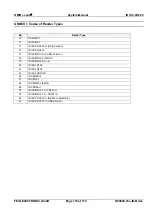
Page 155: ...LR200 FEIG ELECTRONIC GmbH Page 155 of 174 H90692 16e ID B doc ANNEX ANNEX A Codes of Transponder Types Value Transponder type 0x00 Philips I Code 1 0x01 Texas Instruments Tag it HF 0x03 ISO15693 Tran...

Page 156: ...robable local electromagnetic interference present The success or failure of the request min typ max Unit I Code 1 Tag it HF EE Parameter change 1 Block 16 Bytes all 16 Blocks 5 22 340 300 600 ms ms 0...

Page 157: ...onders All times apply to the following parameters ISO MODE 0x0B see chapter CFG8 General Transponder Parameters Fast Mode 1 4 High Data Rate AFI disabled Only ISO Transponder driver active The modula...

Page 158: ...han about 30 Transponders it is better to use the 16 timeslot configuration Switching the value from 1 timeslot configuration to 16 timeslots configuration depends on the application The value of 30 T...

Page 159: ...inventory command 0xB0 0x01 is influenced by the More Bit The More Bit is set if the number of Transponders exceeds 24 So if the More bit is set in the response of the Reader to the inventory command...

Page 160: ...der performance execution time ms Communication time at 115 kBaud ms functions addressed selected addressed selected Stay Quiet 6 8 2 1 Select 8 1 2 1 Reset to Ready 8 2 5 6 2 1 1 3 Get System Informa...

Page 161: ...r is not able to read the Transponder anymore 0x02 Data False CRC16 data error on received data 0x03 Write Error Negative plausibility check of the written data Attempt to write on a read only storing...

Page 162: ...irmware activation required The firmware must be activated first using ISOStart demo program and the command Set Firmware Upgrade The update code must be ordered by Feig Electronic 1 Read the Device I...

Page 163: ...ent is too noisy The RF power doesn t have the configured value The RF final stage has too high a temperature The RF power can be decreased or can be switched off The RF hardware is defective 0x85 Syn...

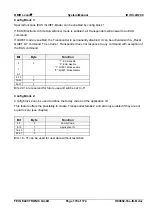
Page 164: ...OBID i scan System Manual ID ISC LR200 FEIG ELECTRONIC GmbH Page 164 of 174 H90692 16e ID B doc 0x95 ISO15693 Error An additional error code for ISO15693 Transponders will be sent with response data...

Page 165: ...nized for example a format error occurred 0x03 The option is not supported 0x0F Unknown error 0x10 The specified block is not available doesn t exist 0x11 The specified block is already locked and thu...

Page 166: ...ftware Version 69 0x69 5 6 0x69 RF Reset 73 0x6A 5 7 0x6A RF ON OFF 74 0x6C 5 8 0x6C Set Noise Level 75 0x6D 5 9 0x6D Get Noise Level 75 0x6E 5 10 0x6E Reader Diagnostic 76 0x6F 5 11 0x6F Base Antenna...

Page 167: ...G5 RF Interface III R W 35 6 3 7 CFG6 CFG7 Selection Mask only I Code EPC Transponder RP WP 35 7 3 7 CFG6 CFG7 Selection Mask only I Code EPC Transponder RP WP 35 Transponder Parameters 8 3 8 CFG8 Gen...

Page 168: ...gurable 5 D0 6 D1 7 D2 8 D3 9 D4 10 D5 11 D6 12 D7 13 D8 14 D9 15 D10 User User Memory read write read only configurable Note During the writing of data to a Transponder ensure that the Transponder st...

Page 169: ...d state no further protective functions can be activated hardware write protected state Bit Byte Function Operation Block I Scan Block I Code 1 0 0 1 r w 0 ro D0 5 1 1 r w 0 ro D1 6 2 1 r w 0 ro D2 7...

Page 170: ...Transponder does not response to any command with exception of the EAS command Bit Byte Function 0 0 1 EAS enable 0 EAS disable 1 1 QUIET Mode enable 0 QUIET Mode disable 2 7 8 15 1 16 23 2 24 31 3 Bi...

Page 171: ...d writing data blocks In Buffered Read Mode BRM Mode however the number of desired data blocks must be multiplied by 2 and entered in DB N CFG11 when using Transponders having 8 byte block size Exampl...

Page 172: ...D i scan System Manual ID ISC LR200 FEIG ELECTRONIC GmbH Page 172 of 174 H90692 16e ID B doc Buffered Read Mode BRM DB Size of the transponder 4 bytes ISO Host Command DB Size of the transponder 8 byt...

Page 173: ...OBID i scan System Manual ID ISC LR200 FEIG ELECTRONIC GmbH Page 173 of 174 H90692 16e ID B doc Buffered Read Mode BRM DB Size of the transponder 8 bytes...

Page 174: ...D ISC M02 71 ID ISC PRH100 U USB Version 72 ID ISC PRH100 73 ID ISC MR100 U USB Version 74 ID ISC MR100 PR100 75 ID ISC MR200 A E 40 ID ISC LR100 41 ID ISC LR200 91 ID ISC LRU1000 80 ID CPR M02 81 ID...

Reviews: