


Identification
Manual
ID ISC.MR102
FEIG ELECTRONIC GmbH
Page 30 of 153
H01113-4e-ID-B.docx
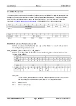
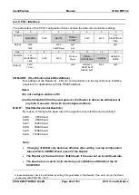
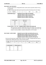
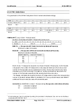
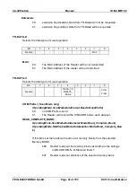
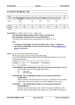
IDLE-STATE / ACTIVE-STATE
One byte each for idle- and tag-detect state is used to set the operation mode of the sig-
nal transmitter.
Bit:
7
6
5
4
3
2
1
0
Function:
Startup
LED
0
0
0
RED
GRN
GRN / RED /Output
(DigitalIO.Signaler.LED.Green.IdleState)
(
DigitalIO.Signaler.LED.Green.ActiveState)
(DigitalIO.Signaler.LED.Red.IdleState)
(DigitalIO.Signaler.LED.Red.ActiveState)
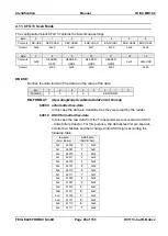
Bit Combination
Signal device
b00
unchanged
b01
on
b10
off
b11
flashing
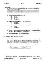
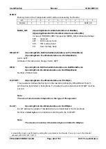
Startup LED
(only idle state)
(DigitalIO.Signaler.Enable_StartupSignal)
When this option is selected, the Reader will switch the LEDs on for two seconds
to indicate that the Reader is ready after the Reader is supplied with power. If the
Reader is reset by software, only both LEDs switch on for 2 seconds.
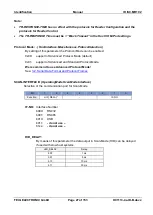
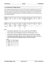
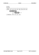
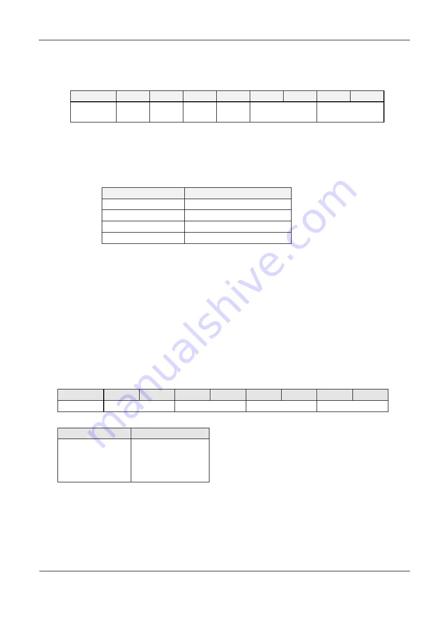
IDLE-FLASH / ACTIV-FLASH:
(DigitalIO.Signaler.LED.Green.IdleFlashFrequency)
DigitalIO.Signaler.LED.Green.ActiveFlashFrequency
(DigitalIO.Signaler.LED.Red.IdleFlashFrequency)
(DigitalIO.Signaler.LED.Red.ActiveFlashFrequency)
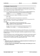
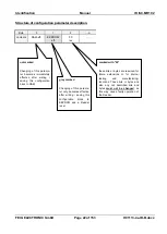
By means of the two bytes "IDLE-FLASH" and "ACTIV-FLASH" the signal transmitter may be
provided with a flashing frequency for idle and active position.
Bit:
7
6
5
4
3
2
1
0
Function:
0
0
RED
GRN
Bit combination
flashing frequency
b11
b10
b01
b00
1 Hz
2 Hz
4 Hz
8 Hz


