951-171-016-EN
Version 032018/11/30
EN
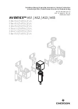
Installation instructions
following machinery directive 2006/42/EC
Lubrication pump ZPU 01/ ZPU 02
Version E Version V Version F
Страница 1: ...951 171 016 EN Version 03 2018 11 30 EN Installation instructions following machinery directive 2006 42 EC Lubrication pump ZPU 01 ZPU 02 Version E Version V Version F ...
Страница 2: ...ional authorities The person empowered to assemble the technical documentation on behalf of the manufacturer is the head of standardization See manufacturer s address Furthermore the following directives and harmonized standards were applied in the respective applicable areas 2011 65 EU RoHS II 2014 30 EU Electromagnetic compatibility Industry 2006 28 EC Electromagnetic compatibility Automotive St...
Страница 3: ... improper or late response to malfunctions unauthorized modifications of the product intent or negligence the use of non original SKF spare parts Liability for loss or damage resulting from the use of our products is limited to the maximum purchase price Liability for con sequential damages of whatever kind is excluded Legal disclosure Manufacturer SKF Lubrication Systems Germany GmbH Manufacturer...
Страница 4: ...1 15 Provision of personal protective equipment 12 1 16 Operation 13 1 17 Emergency stopping of the pump station 13 1 18 Transport installation maintenance malfunctions repair shutdown disposal 13 1 19 Initial commissioning daily start up 14 1 20 Cleaning 15 1 21 Residual risks 16 2 Lubricants 17 2 1 General information 17 2 2 Selection of lubricants 17 2 3 Material compatibility 18 2 4 Ageing of ...
Страница 5: ...1 1 Pump version E 47 12 1 2 Pump versions F and V 48 13 Shutdown and disposal 49 13 1 Temporary shutdown 49 13 2 Final shutdown and disassembly 49 13 3 Disposal 49 14 Spare parts 50 14 1 Motors 380 480 VAC 50 14 2 Motors 380 480 VAC with gear 50 14 3 Motors 500 VAC 51 14 4 Motors 500 VAC with gear 51 14 5 Check valve assy for pump versions F and V 51 14 6 Pump element for pump version E 52 14 7 P...
Страница 6: ...onal protective equipment gloves Wear personal protective equipment protective clothes Wear personal protective equipment safety shoes Release the product General notes Keep unauthorized persons away Disposal recycling Disposal of waste electrical and electronic equipment Warning level Consequence Probability Symbol Meaning DANGER Death serious injury imminent l Chronological guidelines WARNING Se...
Страница 7: ...er e g for example dB A sound pressure level kp kilopound kW kilowatt greater than fpsec feet per second U Voltage less than Conversion factors R resistance plus minus length 1 mm 0 03937 in I current Ø diametre Area 1 cm 0 155 sq in V volt kg kilogram Volume 1 ml 0 0352 fl oz W watt rh relative humidity 1 l 2 11416 pints US AC alternating current approximately Mass 1 kg 2 205 lbs DC direct curren...
Страница 8: ...ware ness of the potential dangers in proper technical condition and according to the information in these instructions Familiarize yourself with the functions and operation of the product The speci fied assembly and operating steps and their sequences must be observed Any unclear points regarding proper condition or correct assembly operation must be clarified Operation is prohibited until issues...
Страница 9: ...tion in areas with aggressive or corrosive ma terials e g high ozone pollution in areas with harmful radiation e g ion ising radiation in an explosion protection zone to supply transport or store hazardous substances and mixtures in accordance with annex I part 2 5 of the CLP regula tion EC 1272 2008 and marked with GHS 01 to GHS 06 and GHS 08 hazard pictograms Use to feed forward or store gases l...
Страница 10: ...s of the pump elements 1 8 Inspections prior to delivery The following inspections were carried out prior to delivery Safety and functional tests In case of electrically driven products electrical inspections following DIN EN 60204 1 2007 VDE 0113 1 2007 1 9 Other applicable documents In addition to these instructions the fol lowing documents must be observed by the respective target group Operati...
Страница 11: ..._______________ 1 12 Notes related to the CE marking CE marking is effected following the require ments of the applied directives 2014 30 EU Electromagnetic compatibility 2011 65 EU RoHS II Directive on the restriction of the use of certain hazardous substances in electrical and electronic equipment Reference on Low Voltage Directive 2014 35 EU The protective regulations of Low Voltage Directive 2...
Страница 12: ...start up operation maintenance repair and disassembly 1 13 3 Specialist in electrics Person with appropriate professional educa tion knowledge and experience to detect and avoid the hazards that may arise from electricity 1 14 Brieing of external technicians Prior to commencing the activities external technicians must be informed by the opera tor of the company safety provisions the applicable acc...
Страница 13: ...of the lubricant Therefore where possible try to carry out maintenance and repair work at room temperature Prior to performing work the product and the machine into which the product will be integrated must be depressur ized and secured against unauthorized activation Ensure through suitable measures that movable or detached parts are immobi lized during the work and that no limbs can be caught in...
Страница 14: ...em may be subjected to torsion shear or bending Check all parts prior to their usage for contamination and clean if necessary Lubricant lines should be primed with lubricant prior to installation This makes the subsequent ventilation of the system easier Observe the specified tightening torques When tightening use a calibrated torque wrench When working with heavy parts use suit able lifting tools...
Страница 15: ...eaning agents Only use non flammable cleaning agents suitable for the purpose Do not use aggressive cleaning agents Do not use steam jet or high pressure cleaners Electrical components may be damaged Observe the IP protection class Cleaning work may not be carried out on energized components Mark damp areas accordingly ...
Страница 16: ...njury material damage due to electric shock because of damage to the connection cable B C D E F G H Check the connection cable with regard to damages before the first usage and then at regular intervals Do not mount cable to moving parts or friction points If this cannot be avoided use spring coils respectively protective conduits Personal injury damage to material due to spilled or leaked lubrica...
Страница 17: ...the lubricant supplier based on the re quirement profile defined Should you have little or no experience with the selection of lubricants for centralized lu brication systems please contact SKF If required we will be glad to support cus tomers to select suitable components for feeding the selected lubricant and to plan and design their centralized lubrication system You will avoid possible costly ...
Страница 18: ...to chemical or physical ageing We recommend that you undertake this inspection already after a machine downtime of 1 week If doubts arise as to the suitability of the lu bricant please replace it prior to re commis sioning and if necessary undertake initial lubrication manually It is possible for lubricants to be tested in the company s laboratory for their suitability for being pumped in centrali...
Страница 19: ...or for low level indication purposes While the pump operates the stirring paddle rotates to homogenize and vent the lubricant The stirring paddle s lower part pushes the lubricant towards the pump elements thus im proving transportability 2 Pump element Supplies lubricant into the lubricant feed line 3 Pump housing 4 Gear The gear reduces the motor speed to the speed required for the pump s eccent...
Страница 20: ...ional description Overview version E Fig 2 Versions Version E Consists of 1 or 2 pump elements that are fitted directly into the pump housing ZPU 01 ZPU 02 pump versions E are used mainly for progressive systems with one or two lubrication circuits ...
Страница 21: ...rview functional description Overview version V Fig 3 Version V Consists of a bridge to combine the lubricant volume and a pressure gauge ZPU 01 ZPU 02 pump versions V are used mainly for progressive systems with one lubrica tion circuit ...
Страница 22: ...scription Overview version F Fig 4 Version F Consists of a bridge to combine the lubricant volume a filter block a pressure gauge and a pressure control valve ZPU 01 ZPU 02 pump versions F are used mainly for dual line systems with one lubrica tion circuit ...
Страница 23: ...ed with suitable pressure control valves ex works Outlet fitting Version E G1 4 Version E or F G3 8 for tube 10 mm Installation position vertical i e reservoir at top Deviation 5 Sound pressure level 70 dB A Type of protection IP 55 Weight of the empty pump approx 19 kg Number of pump elements ZPU 01 1 ZPU 02 2 Filling of the pump via reservoir lid Approved lubricants mineral oils basic oils respe...
Страница 24: ... lN 1 22 0 7 A Size 63 Starting current 2 5 x rated current A Design B14 Performance factor cos j 0 69 Shaft Ø 11x 23 mm Motor for gear M100 M490 Part number Type of motor Manufacturer 245 13914 1 TN 63 Neri Rated voltage V 230 400 265 460 VAC Efficiency h 62 Circuit Insulation class F Rated frequency f 50 60 Hz Type of protection IP 55 Rated power P 0 25 0 29 KW Flange Ø 90 mm Rated speed n 1334 ...
Страница 25: ... B14 Starting current 2 5 x rated current A Shaft Ø 11x 23 mm Performance factor cos j 0 7 Ratio i 100 Efficiency h 54 Part number Type of motor Manufacturer 245 13916 1 DIC 63L4 Motori Elettrici Rated voltage V 220 420 250 480 VAC Insulation class F Circuit Type of protection IP 55 Rated frequency f 50 60 Hz Flange Ø 90 mm Rated power P 0 25 0 29 KW Operating mode S1 Rated speed n 1500 1800 rpm 1...
Страница 26: ...265 460 VAC Insulation class F Circuit Type of protection IP 55 Rated frequency f 50 60 Hz Flange Ø 90 mm Rated power P 0 18 0 21 KW Operating mode S1 Rated speed n 1380 1630 rpm 1 Size 63 Nominal current lN 1 22 0 7 A Design B14 Starting current 2 6 x rated current A Shaft Ø 11x 23 mm Performance factor cos j 0 68 Ratio i 490 Efficiency h 54 3 ...
Страница 27: ...0 6 A Design B14 Starting current 2 5 x rated current A Shaft Ø 11x 23 mm Performance factor cos j 0 69 Efficiency h 62 Motor for gear M100 M490 Part number Type of motor Manufacturer 245 13120 1 TN63 Neri Rated voltage V 290 500 VAC Insulation class F Type of protection IP 55 Rated frequency f 50 Hz Flange Ø 90 mm Rated power P 0 25 KW Operating mode S1 Rated speed n 1400 rpm 1 Size 63 Nominal cu...
Страница 28: ...N 1 0 0 6 A Design B14 Starting current 2 5 x rated current A Shaft Ø 11x 23 mm Performance factor cos j 0 68 Ratio i 100 Efficiency h 54 Part number Type of motor Manufacturer 245 13922 1 T63C 025 4p B14 Neri Motori Rated voltage V 290 500 VAC Insulation class F Type of protection IP 55 Rated frequency f 50 Hz Flange Ø 90 mm Rated power P 0 25 KW Operating mode S1 Rated speed n 1360 rpm 1 Size 63...
Страница 29: ...290 500 VAC Insulation class F Circuit Type of protection IP 55 Rated frequency f 50 Hz Flange Ø 90 mm Rated power P 0 18 KW Operating mode S1 Rated speed n 1360 rpm 1 Size 63 Nominal current lN 1 0 0 6 A Design B14 Starting current 2 5 x rated current A Shaft Ø 11x 23 mm Performance factor cos j 0 68 Ratio i 490 Efficiency h 54 ...
Страница 30: ...s delay 300 ms T ypeofprotectionfollowingEN60529 IP 65 Rangeofoperatingtemperatures 40 C to 70 C Switch points High level indication D1 65 mm low level indication D2 corresponding to the reservoir size pre low level indica tion D3 programmable on customer request pre set to 10 mm above low level optional use possible Compliance with standards EN 60947 5 2 1 2 4 3 5 1 UB brown U 1 2 4 5 3 3 UB blue...
Страница 31: ... control valve with bridge 30 Nm 3 Nm Pump version E Fitting for supply line with bridge 30 Nm 3 Nm Pump element with pump housing 30 Nm 3 Nm Hollow screw for filter block 100 Nm 10 Nm Pump version F Pump cylinder with pump housing 30 Nm 3 Nm Check valve with pump cylinder 30 Nm 3 Nm Pressure gauge with bridge 55 Nm 5 Nm Bridge with filter block 10 Nm 1 Nm Pressure control valve with filter block ...
Страница 32: ... Drive assy E Additional motor specification M Three phase motor with flange Ø 90 mm additional designation see E 000 Pump without motor but with flange Ø 90 mm 100 Gear ratio i 1 100 500 Motor 500 VAC 50 Hz 049 Gear ratio i 1 049 380 420 Motor for 380 420 VAC 50 Hz and 440 480 VAC 60 Hz 490 Gear ratio i 1 490 440 480 C Reservoir versions 10 XYBU 10L reservoir for grease and oil with level monitor...
Страница 33: ...s on the packaging as follows 5 3 Storage SKF products are subject to the following storage conditions dry dust and vibration free in closed premises no corrosive aggressive materials at the place of storage e g UV rays ozone protected against pests and animals in sects rodents etc possibly in the original product packaging shielded from nearby sources of heat and coldness in case of high temperat...
Страница 34: ...of heat and coldness Observe the product s IP type of protection Adhere to safety distances and legal pre scriptions on assembly and prevention of accidents Possibly existing visual monitoring de vices e g pressure gauges MIN MAX markings oil level sight glasses or piston detectors must be clearly visible Observe prescriptions in theTechnical data chapter 4 regarding the installation position 6 2 ...
Страница 35: ... free space of at least 100 mm into each direction in addition to the stated dimensions Pump version E V F H1 10L 514 513 514 H2 30L 754 754 754 B1 10L 380 380 380 B2 30L 440 440 440 T1 10L 280 343 330 T2 30L 330 390 377 D1 10L Ø 220 Ø 220 Ø 220 D2 30L Ø 324 Ø 324 Ø 324 additional free space requirement distance to the air inlet of the motor 40 mm additional free space requirement to open the hous...
Страница 36: ...71 016 Version 03 Installation bores Fig 6 A 6 3 2 Installation bores The product is fastened on the 4 mounting bores A on an even surface of the pump housing Fastening is done by means of 4 screws type M8 property class 8 8 ...
Страница 37: ...e it against being switched on Verify that no power is being applied Earth and short circuit the product Where needed cover neighbour ing units that are live Carry out the electrical connection of the pump following the indications made by the motor manufacturer L1 L2 L2 U1 V1 W1 W2 U2 V2 Star connection L1 L2 L2 U1 V1 W1 W2 U2 V2 Delta connection Connection diagram see motor terminal box Connect ...
Страница 38: ...nd smooth operation Use clean components and primed lubri cation lines only The main lubrication line should be laid preferably rising with a possibility to vent it at its highest point Lubrication lines shall generally be laid in such way that there can never be created air pockets at any point Mount the lubricant metering devices at the end of the main lubrication line in such way that the outle...
Страница 39: ...e that no dirt enters the reservoir during the filling procedure Switch the pump off Open the reservoir lid 1a Remove contaminations from the res ervoir lid and from the ultrasonic sen sor if any Filling via the reservoir lid Fig 8 In case of reservoirs with ultra sonic sensor The ultrasonic sensor must not get in contact with lubricant The distance between the lubri cant and the ultrasonic sensor...
Страница 40: ...ible damage contamination and corrosion Any dismantled protection and monitoring equipment has been reassembled and checked for correct function All warning labels on the product are available and in proper condition 7 2 Inspections during initial start up No unusual noises vibrations accumulation of moisture or odours present No unwanted escape of lubricant from connections leakages Lubricant is ...
Страница 41: ...e greatest possible extent Basically activities during standard opera tion are limited to the control of the filling level and the timely refilling of lubricant as well as the outside cleaning of the product in case of contamination 8 1 Reill lubricant Description see corresponding chapter 6 6 1 ...
Страница 42: ...cleaners or high pressure cleaners only in accordance with the IP protection class of the pump Otherwise electrical components may be damaged Cleaning execution required personal protective equipment cleaning agents and devices following the valid operational regulations of the operator 9 2 Exterior cleaning Mark and secure wet areas Keep unauthorized persons away Thorough cleaning of all outer su...
Страница 43: ...e data of the previously indicated connections correspond to the specifications stated in theTechnical data All components such as lubrication lines and metering devices have been correctly installed Product protected with adequate pressure relief valve No visible damage contamination and corrosion Any dismantled protection and monitoring equipment has been reassembled and checked for correct func...
Страница 44: ...g grease suitable for the operating temperature range 10 2 3 Replacement of the bearing grease Given normal load conditions operation at nominal speed and under normal envi ronmental conditions replace the bearing grease as follows Motor bipolar multipolar service hours 10 000 20 000 In case of deviating conditions e g operation with a frequency converter the replacement interval reduces in accord...
Страница 45: ...es not supply lubricant or supplies an insufficient amount of lubricant Blockade fault within the centralized lubrication system Defective check valve Defective pressure relief valve Suction bore of pump element is clogged Defective pump element Too high lubricant consistency at low temperatures In case of version F Contaminated filter mostly visible from a fluttering display of the pressure gauge...
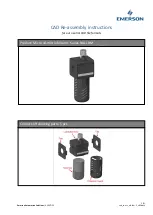
Страница 46: ...h ring see Fig 9 Turn the stirring paddle to the opposite side of the pump ele ment This facilitates mounting the piston into the notch of the catch ring WARNING Risk of injury Before carrying out any repair work take at least the following safety measures Keep unauthorized persons away Mark and secure work area Depressurize the product Disconnect the product from the power supply and secure it ag...
Страница 47: ...out of the pump element 2 Insert the pump element obliquely until the piston is located above the catch ring Now hold the pump element horizontally so that the piston of the pump element engages in the notch of the catch ring Screw in the pump element 2 Tightening torque 35 Nm Then check the pump element for proper function To do so switch the pump on and check whether the pump element supplies lu...
Страница 48: ...l the piston of the new pump cylinder about 30 mm out of the pump cylinder Insert the pump element 7 obliquely until the piston is located above the catch ring see Fig 11 Now hold the pump cylinder 7 hori zontally so that the piston of the pump element engages in the notch of the catch ring Screw in the pump cylinder 7 Position the bridge 9 on the pump cyl inder 7 Screw the blind stud 8a into the ...
Страница 49: ...l of products con taminated with lubricant must be effected vi a licensed waste disposal contractor in ac cordance with environmental requirements and waste disposal regulations as well as local authority requirements The specific classification of the waste is in the waste producer s responsibility as the European Waste Catalogue provides differ ent waste disposal codes for the same type of waste...
Страница 50: ...ts are not allowed Fig 13 14 1 Motors 380 480 V AC Designation Qty Part number Motor for gear M100 M490 0 18 kW 0 21 kW 1 245 13913 1 Motor for gear M049 0 25 kW 0 29 kW 1 245 13914 1 Fig 14 14 2 Motors 380 480 V AC with gear Designation Qty Part number Motor with gear M100 0 18 kW 0 21 kW 1 245 13915 1 Motor with gear M049 0 25 kW 0 25 kW 1 245 13916 1 Motor with gear M490 0 18 kW 0 21 kW 1 245 1...
Страница 51: ... Motor for gear M049 0 25 kW 1 245 13920 1 Fig 16 14 4 Motors 500 V AC with gear Designation Qty Part number Motor with gear M100 0 18 kW 1 245 13921 1 Motor with gear M049 0 25 kW 1 245 13922 1 Motor with gear M490 0 18 kW 1 245 13923 1 Fig 17 14 5 Check valve assy for pump versions F and V Designation Qty Part number Check valve assy 1 500 30012 3 ...
Страница 52: ...00 30018 3 Fig 19 14 7 Pressure control valve for pump version E Designation Qty Part number Pressure control valve 10 mm 350 bar 1 624 25483 1 Pressure control valve 10 mm 400 bar 1 624 28073 1 Fig 20 14 8 Gear Designation Qty Part number Gear ratio i 100 1 1 246 14145 1 Gear ratio i 490 1 1 246 14146 1 Gear ratio i 049 1 1 246 14145 2 ...
Страница 53: ...ment 350 bar Bridge assy for version F with one pump element 400 bar Consisting of Item 1 Bridge with filter block and pressure gauge Item 2 Valve assy Item 3 Pump cylinder assy Item 4 Sealing ring 2x Item 5 Blind cylinder Item 6 Locking screw Item 7 O ring 2x 1 600 26787 1 1 1 1 1 2 1 1 2 600 77912 1 Fig 22 14 11 Ultrasonic sensor Designation Stk Sachnummer Ultrasonic sensor for reservoir size 10...
Страница 54: ...Item 3 Pump cylinder assy Item 4 Sealing ring 2x 1 600 26788 1 1 1 1 2 2 600 77913 1 Fig 24 Fig 25 14 13 Bridge assy for version V with one pump element Designation Qty Part number Bridge assy for version V with one pump element 350 bar Bridge assy for version V with one pump element 400 bar Consisting of Item 1 Bridge with filter block and pressure gauge Item 2 Valve assy Item 3 Pump cylinder ass...
Страница 55: ... two pump elements 350 bar Bridge assy for version V with two pump elements 400 bar Consisting of Item 1 Bridge with filter block and pressure gauge Item 2 Valve assy Item 3 Pump cylinder assy Item 4 Sealing ring 2x 1 600 26786 1 1 1 1 2 2 600 77915 1 Fig 26 Fig 27 14 15 Sealing ring Designation Qty Part number Sealing ring Ø 60 x 90 x 0 5 1 306 19415 1 14 14 ...
Страница 56: ... 1 306 19640 1 14 17 Fig 29 14 17 Pressure gauge for pump versions V and F Designation Qty Part number Pressure gauge 0 600 bar 1 500 32143 1 Fig 28 14 16 Parts for strainer for version F Designation Qty Part number Rubber lined sealing ring Ø 34 3 x 43 x 2 1 220 12238 3 Coarse strainer 1 428 21544 1 Fine strainer 1 428 21545 1 ...
Страница 57: ...Notes ...
Страница 58: ...rsion 03 2018 11 30 SKF Lubrication Systems Germany GmbH Walldorf Facilities Heinrich Hertz Str 2 8 DE 69190 Walldorf Phone 49 0 6227 33 0 Fax 49 0 6227 33 259 E mail Lubrication germany skf com www skf com lubrication ...