


Identification
Manual
ID ISC.MR102
FEIG ELECTRONIC GmbH
Page 139 of 153
H01113-4e-ID-B.docx
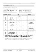
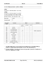
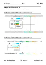
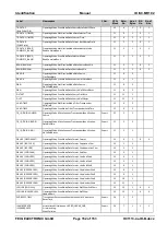
9.1.1. DATA Structure in Notification Mode
Requested number of data sets from the data buffer. Only selected data will be transferred to the
host. See chapter
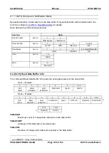
Each data set has the following structure:
Data Type
DATA
Record Length
byte no.
1
2
MSB RecLen
LSB RecLen
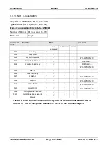
Serial Number
byte no.
1
2
3
3+LEN
TR-TYP
IDDT
IDD-LEN
IDD
Data Blocks
byte no.
1
2
3
4…4+DB-N*DB-SIZE
DB-N
DB-SIZE
DB
Timer
byte no.
1...4
TIMER
MAC
byte no.
6
MAC-ADR
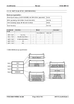
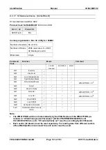
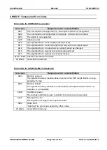
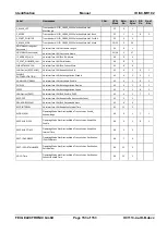
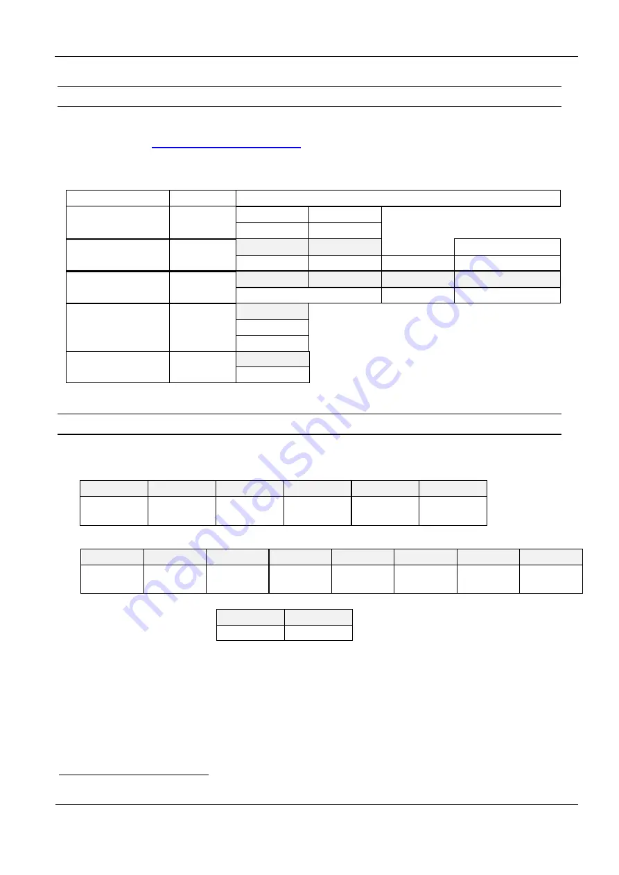
9.2. [0x31] Read Data Buffer Info
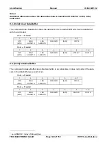
The command Read Data Buffer Info reads the actual parameters of the data buffer.
Host
Reader
1
2
3
4
5
6...7
STX
(0x02)
MSB
ALENGTH
LSB
ALENGTH
COM-ADR
[0x31]
CRC16
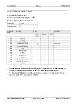
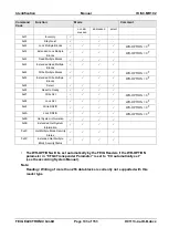
Host
Reader
1
2
3
4
5
6
7...8
9,10
STX
(0x02)
MSB
ALENGTH
LSB
ALENGTH
COM-ADR
[0x31]
STATUS
21
TAB-SIZE
TAB-START
11,12
13,14
TAB-LEN
CRC16
TAB-SIZE:
Maximum count of Transponder data sets in the data buffer.
TAB-START:
Address of first Data Set in the data buffer.
TAB-LEN:
Number of Transponder data sets reserved in the data buffer.
21