19
Federal Signal
signaling.fedsig.com
Servicing the LED Module
NOTE:
The bi-color LED service kit option is provided only for factory-LED-installed stations in either 6, 12, 24, or 48 Vdc
applications noted as such on their model # : CP-BG-x-x-x-xxx-XX-x or CP-PB-x-x-x-xxx-XX-xx where XX = 06, 12, 24, or
48 Vdc on stations where the LED is present. If XX = 00, no LED is present within the unit.
Replacement service kits are NOT to be installed on stations with XX = 00 within their model number. Failure to
observe this warning may lead to property damage, serious injury, or death.
In the event that the LED is not lighting in either normal (green) or alarm (red) state within an LED station, it should be
replaced along with its series resistor with the proper kit, depending on its applicable voltage (See Table 2 on “Table
2 Call Points Field Installed Service/Accessory Kits” on page 23 for the available kits.) The kit consists of the LED
module and its corresponding series resistor, along with two wire ties.
Tools needed (after internal access):
•
Wire cutter
•
#1 Philips screwdriver
To service the module:
1.
Ensure that the power is off and the station is in NORMAL mode.
2.
Open the station so that the front housing’s internal side is shown (see “Opening / Closing the Call Point for
Internal Access” on page 4), along with the internal side of the rear housing. Remove the three screws holding
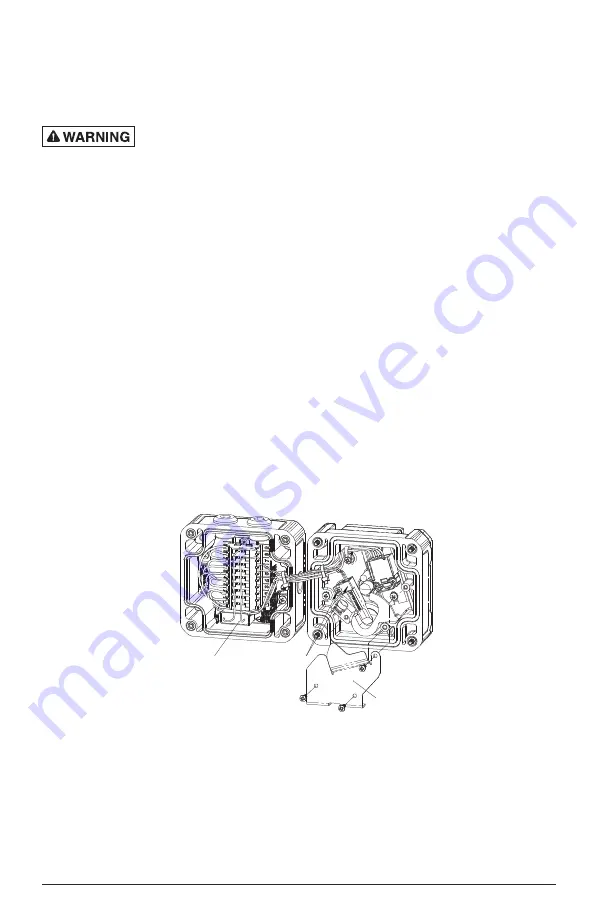
the switch shroud in place to gain easier access to the LED module:
3.
Remove the mounting screw holding the LED module in place (set it aside, as it will be needed for installing the
replacement), and clip and remove the wire ties bundling the three LED wires to the switch wires.
Figure 27 Station interior
SWITCH SHROUD
LED MODULE
W/MOUNTING SCREW
LED SERIES
RESISTOR MODULE
FRONT HOUSING
REAR HOUSING
4.
Carefully remove the LED module by lifting it from its recessed relief in the front housing.
5.
Remove the three LED 22 AWG leads from the cage clamp wiring block:
• Green wire @ terminal #5
• Red wire @ terminal #6
• Black wire @ terminal #7
6.
Remove the corresponding series resistor module (snap tabs) whose leads are attached to terminals #8 and #9 of
the block.


