


Page 5 of 35
Rev. 1.03
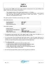
The fire-prevention
CFN
control panel was designed in observance to the rules EN54-2 and
EN54-4, and it has the following characteristics:
ü
The available versions of the control panel are at 2 – 4 – 6 zones.
ü
It is possible to install on a single zone up to 20 active points (detectors, points supplied
from zone line) plus passive points (buttons, smoke linear barrier, ...) until to a
maximum of 32 total points for zone.
The power supply to the device occurs through only 2 cables.
Connectible detectors:
Smoke detectors:
RF1, SOD
Heat detectors:
RT, TV
Multi-criteria detectors:
RFT1
Connectible modules:
Manual buttons:
P, P1, P5
Linear barrier smoke detectors:
RLF1
GAS detectors:
GMR, GGR, GCR
Relay output modules:
All devices with a relay output
•
The detectors must be plain with a low power supply of 50
µ
A, when the detector is in
normally functioning. If it goes to alarm mode, the current is 25mA.
•
The control panel have the panel with leds and buttons to view the status signal and to
programmer the control panel. Faults and alarms are visualize through the led luminous
and they are signal through the buzzer acoustic of control panel them.
•
The control panel has:
o
a supervised siren output for the alarm signalling (out1);
o
a supervised siren output for the alarm/pre-alarm signalling (out2);
o
a relay output C-NO-NC for the alarm signalling (Relay1);
o
a relay output C-NO-NC normally on for the fault signalling (Relay2);
o
six open collector outputs of zone alarm.
•
All control panel programming must be made through the panel buttons.
PART 2
DETAILS


