background image

14

6

Warning

Warning

Function

6 MAINTENANCE AND REPAIR

Always disconnect the unit from the mains!

The company operating the unit must ensure that the unit is always operated in perfect condition only. Ensure regular

maintenance and checking of the technical equipment. In the case of repair work or activities for setting the unit

back into operation, additional measures - such as preventing access by unauthorised persons - are absolutely

essential. Only duly authorized people are allowed to work on the unit, therefore please refer to your specialized

dealer or to uwe. The unit is not to be worked upon in such a way that its safety is affected. Always obtain genuine

spare parts through your dealer or the uwe company. Do not operate the unit without acrylic sheets.
6.1 Changing the Acrylic Sheet

The acrylic sheets are special types of glass which are highly transparent to UV light.

Therefore, when replacing them, you must not use window glass or ordinary acrylic glass, as these

types of glass filter out the UV rays completely or partially. Always obtain the genuine acrylic sheets

from your dealer or from the manufacturer of the unit.

When a replacement is delivered, the acrylic sheet is covered with a protective covering on both sides. Before

installing in the tanning units, pull off the protective covering. There is a sticker on the acrylic sheet with important

information. Please note the information and then remove the sticker. Do not operate units without acrylic sheets,

because otherwise the cooling of the lamps is no longer assured.

If damage or injury occurs, the manufacturer cannot accept liability.

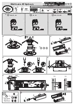
Acrylic sheet lounger (1), installation and removal (picture 4)

The acrylic sheet of the lounger has a mat finish on its underside. Do not polish that mat side of the acrylic sheet

with paste polish.
The acrylic sheet lounger (1) rests free on the pipeframe. Lift the acrylic sheet together with someone else, and

take down the acrylic sheet.
When re-installing, place the acrylic sheet over the pipeframe, so that its surrounding border slides over the

flaps of the covering hoods (56, 57, 58).

Acrylic sheet tanning arms (43), installation and removal (picture 6)

Unscrew the flat-headed screw M 4 (65), with which the acrylic sheet (43) is fastened together over a square

on the light-casing. Then turn the acrylic sheet a little bit out and pull the acrylic sheet away forward in

longitudinal direction. When reinstalling, push the acrylic sheet of the lateral tanning arms over the fastening

wedge (104, picture 6).

Push the acrylic sheet of the upper tanning arm over the fastening wedge (44, picture 3) of the covering hood

(40). Lift the acrylic sheet in direction of the tanning arm. Tighten up again the flat-headed screw (65).

Al ways take care during the installation, that the acrylic sheet lays in the slot of the covering

hood (66).

65

43

79

68

72

70

104

99    71

102

69

68

70
72

67

Summary of Contents for SunBoard XTT

Page 1: ...1 INDOOR TANNING EQUIPMENT CARE USE AND INSTALLATION INSTRUCTIONS Model SunBoard XTT PC MARKETING 1040 WILT AVENUE RIDGEFIELD NJ 07657 1 800 FAST TAN...

Page 2: ...4 1 5 Product Liability 4 1 6 Emergency Procedure 4 1 7 Explanation of Danger Symbols 4 2 OPERATION I INFORMATION FOR THE USER OF THE UNIT 5 6 2 1 Starting to sunbathe 5 2 2 Important Technical Detai...

Page 3: ...week onward USE PROTECTIVE EYEWEAR WHENEVER THE EQUIPMENT IS ENERGIZED READ THE INSTRUCTION BOOKLET BEFORE USING THIS PRODUCT WARNING If you have been diagnosed by a physician as being allergic to th...

Page 4: ...TE AND ARE DESIGNED FOR USE WITH INDOOR TANNING EQUIPMENT FAILURE TO COMPLY WITH RECOMMENDATIONS AND WARNINGS STATED ABOVE MAY VOID THE MANUFACTURER S WARRANTY WARNING THIS UNIT MUST NOT BE USED IF TH...

Page 5: ...ilter disc when exchanging the burner the electrical circuit will be interrupted and the unit can not be started see Section 8 BreakSafe Speakers 34 picture 3 There are two speakers so that you can en...

Page 6: ...on the pallet The Plexiglas plate lounger 1 picture 4 lies free on top of the pipeframe 2 Lift down the Plexiglas plate together with someone If the pipeframe is fastened together with the tripod unwi...

Page 7: ...the tripod Secure the screws 28 of the foot casing with toothed disks A8 4 29 and octagonal nuts M8 30 secure the screws 31 of the light casing with washers 32 having 25 mm in external diameter and w...

Page 8: ...the support 44 of the covering hood 40 After this secure coming from the tripod the four pins 64 with disks 46 having an external diameter of 25mm and with hexagonal nuts 45 You really must tighten u...

Page 9: ...the right side of the tripod This tanning arm has an 18 poled cable X6 53 with plug and the BreakSafe cable X6a these cables you have to pull through down wards into the footrack The plug X6 53 will...

Page 10: ...to the tripod Then arrange the three covering hoods 56 57 58 around the pipeframe The two covering hoods 56 and 58 arranged on the sides of the pipeframe will be fixed onto the tripod by a strip faste...

Page 11: ...ffective ventilation can be found in the brochure AIR CONDITIONING TIPS which is available from your dealer or from us 3 4 Electrical Connection Important The connection work may only be done by an el...

Page 12: ...e even We reserve the right to make technical changes LAMP CONFIGURATION If the lamps are not placed in the correct position this may result in a loss of performance and lifetime Please ensure to use...

Page 13: ...ents Provide protective glasses and ensure that they are used Highlight the need to adjust the length of the sunbathing period depending on skin type Keep user instructions at hand Put up the safety i...

Page 14: ...n the acrylic sheet with important information Please note the information and then remove the sticker Do not operate units without acrylic sheets because otherwise the cooling of the lamps is no long...

Page 15: ...int on both sides Pull off the disk holder from the front using both hands Hold the high pressure lamp by the rectangular base and press it out of the socket Cleaning the Reflector Clean the reflector...

Page 16: ...ng the High Pressure lamp Hold the new high pressure lamp by the base 102 Insert the lamp into the holder 77 Attention The contact pins 79 of the socket have different diameters Please insert accordin...

Page 17: ...ilter so that it is only necessary to clean the components inside the unit e g such as filter plates infrequently The particles filtered out eventually clog the filter after extended use and thus redu...

Page 18: ...k holder 75 picture 7 and the reflector 87 If this does not help there is an electrical defect in the unit Checking up by uwe or by another firm named by uwe The illumination light does not shine exch...

Page 19: ...ses They should not be thrown together with the regular waste The local offices will inform you where the burner could be properly wasted Unit Faulty units should be disposed of according to local reg...

Page 20: ...20 ID NR 265 360 03 03 PC MARKETING 1040 WILT AVENUE RIDGEFIELD NJ 07657 1 800 FAST TAN...

Reviews: