www.fastech.co.kr
Other Operation Functions
48
V06.01.
3
x.xx : -
2,147,483,648 ~
2,147,483,647(Start Position), 0 ~ 2,147,483,647(Pulse Period)
Trigger output is output normally when the pulse period is over 2 [ms]
(including
pulse width)
Pulse period [ms] = pulse period [pulse] / movement speed [pps] * 1000 (unit
conversion constant [s]-> [ms]) + pulse width [ms]
ex) Pulse period: 100 [pulse], moving speed: 10,000 [pps], pulse width: 1 [ms]
Pulse period [ms] = 100/10000 * 1000 + 1= 11
If the start / end is not set to '0' and the move command with the target position
is sent, the trigger output will be activated.
Start / end is automatically set to '0' if a command without a target position is
delivered, such as Jog command, after trigger output execution.
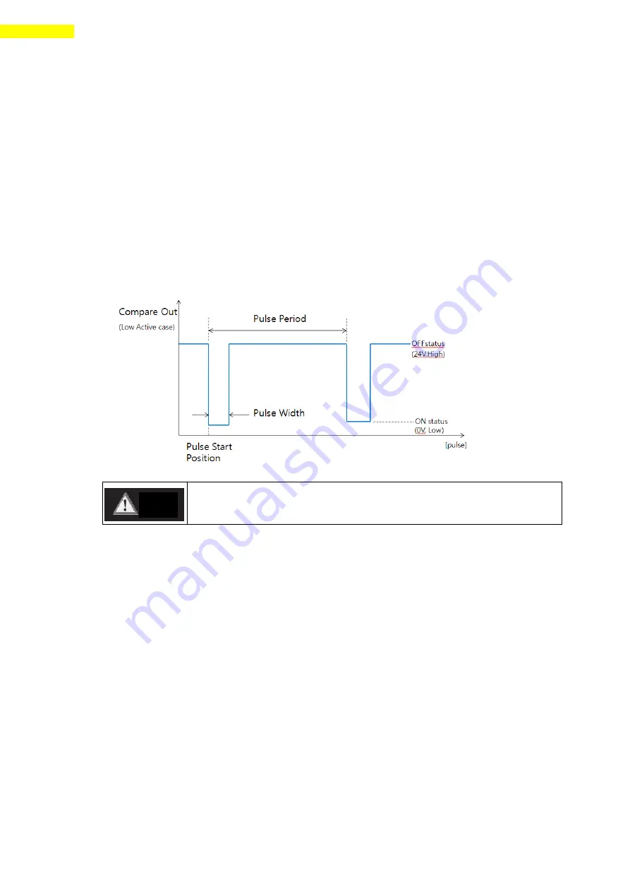
(2) Output signal
This output pin of CN1 connector for Trigger Pulse is fixed to 「Compare Out」and
the signal diagram is as follows.
(
3)
Out
put Status Check
By using DLL program, the user can check the trigger pulse output status.
Refer to
「User Manual – Communication Function」
.
The pulse is output only in bigger position area than ‘pulse starts
position ‘and is output in both motion directions.
Caution
Summary of Contents for Ezi-Step II Plus-E
Page 1: ... Rev 03 User Manual Text ...
Page 8: ...www fastech co kr Specifications of the Drive 8 ...
Page 11: ...www fastech co kr 11 Specifications size of the Motor Motor Size 3 2 ...
Page 12: ...www fastech co kr Specifications size of the Motor 12 ...
Page 17: ...www fastech co kr 17 Configuration 2 86 mm motor drive ...
Page 19: ...www fastech co kr 19 Configuration 2 86 mm Motor Drive ...
Page 67: ...www fastech co kr 67 Appendix Brake Installed Motor Specification and Size 12 3 ...


