-32-
6.3.5 Life time of Gearhead and Service factor
•
The lifetime of the gearhead is usually determined by the method of supporting the shaft, but
since the load is often changed, the factor of the service element is used depending on the
type of load.
•
If the gearhead is used within the permissible torque, it can be used up to 5000 hours when the
rated life time is ball bearing type.
•
The rated life time is the time until the decelerator stops when the motor is operated under the
following conditions and the motor torque can not be transmitted to the gearhead shaft
1. When used within the permissible torque
2. In case of operation same rotation direction without load change.
3. In case of operation 8 hours per day
4. Bearing temperature : 80℃ ( Ball bearing type )
Service factor of above conditions is SF=1
If using ball bearing type gear head by 24 hours, service factor will be 1.5 so life time will be
reduce to 1/1.5.
Therefore, select the motor and gearhead with the maximum permissible torque
considering the service factor.
6.3.6 Maximum permissible torque of gearhead
•
The output torque of the gearhead varies greatly in proportion to the gear ratio, but the load
torque applied to the reducer is limited by the gear material and other conditions.
• This is defined as the maximum permissible torque and is based on the size of gearhead and
gear ratio of the gearhead. Use it within permissible torque range.
𝑇
𝐺
= 𝑇
𝑀
× 𝑖 × 𝜏
(Gearhead torque = Motor qorque X gear ratio X Transmission efficiency of gearhead)
• Even if the gearhead torque is large value by calculation, do not use it at a load that exceeds
the maximum permissible torque.
Summary of Contents for Ezi-SPEED ESD-30-C
Page 1: ......
Page 9: ...9 2 Characteristics 2 1 Part number...
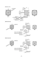
Page 15: ...15 3 2 Dimensions 30W 60W 120W Drive 200W 400W Drive...
Page 18: ...18 ESM 90 H 120 ESM 104 H 200 ESM 104 H 400...
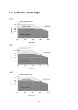
Page 19: ...19 4 3 Characteristics of motor torque 30W 60W 120W...
Page 20: ...20 200W 400W...
Page 63: ...63 8 2 Setting and 7 segments display 1 Monitor mode...
Page 64: ...64 2 Input Output setting mode...
Page 65: ...65 3 Parameter setting mode 1page...
Page 66: ...66 3 Parameter setting mode 2page...
Page 67: ...67 3 Parameter setting mode 3page...
Page 68: ...68 3 Parameter setting mode 4page...
Page 69: ...69 4 NVM saving mode...

