-39-
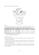
▣ Use the rear side as the mounting surface
▣ Note
When installing the gearhead by using its rear side as the mounting surface, prevent contact betw
een the mounting palte and motor by keeping dimension “E” below the specified value.
Part Number
ØA
ØB H8
ØC
ØD
E
ESG-60-H-R□-H
70
34+(0~0.039)
5.5
25
29
ESG-80-H-R□-H
94
38+(0~0.039)
6.5
30
39
ESG-90-H-R□-H
104
50+(0~0.039)
8.5
35
44
* □ of part number indicates a number of gear ratio.
* Unit of mounting holes dimension is [mm]
▣ Mount the load shaft
• When mounting the load shaft on the hollow shaft, align the centerline of the hollow shaft with
the centerline of the load shaft.
• The hollow shaft key is grooving. Please the machining key grooving on the load shaft. Using
the supplied parallel key between the hollow shaft and the load shaft for fixed. The load shaft
tolerance is recommended [h7]
• If the motor received impact due to instantaneous stop or is subject to a large overhung load,
please use stepped load shaft and fix with end plate. Please refer the detail of the fixing method
using the end plate.
Summary of Contents for Ezi-SPEED ESD-30-C
Page 1: ......
Page 9: ...9 2 Characteristics 2 1 Part number...
Page 15: ...15 3 2 Dimensions 30W 60W 120W Drive 200W 400W Drive...
Page 18: ...18 ESM 90 H 120 ESM 104 H 200 ESM 104 H 400...
Page 19: ...19 4 3 Characteristics of motor torque 30W 60W 120W...
Page 20: ...20 200W 400W...
Page 63: ...63 8 2 Setting and 7 segments display 1 Monitor mode...
Page 64: ...64 2 Input Output setting mode...
Page 65: ...65 3 Parameter setting mode 1page...
Page 66: ...66 3 Parameter setting mode 2page...
Page 67: ...67 3 Parameter setting mode 3page...
Page 68: ...68 3 Parameter setting mode 4page...
Page 69: ...69 4 NVM saving mode...


