2. Installation
2.4.4
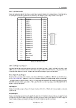
I/O Connector
Input and output signals of the drive are all photo-coupler protected, the signal status of internal photo-
couplers [ON:conduction], [OFF:Non-conduction], not displaying the voltage levels of the signal.
No.
Function
I/O
1
LIMIT+
Input
2
LIMIT-
Input
3
ORIGIN
Input
4
Digital In1
Input
5
Digital In2
Input
6
Digital In3
Input
7
Digital In4
Input
8
Digital In5
Input
9
Digital In6
Input
10
Digital Out1
Output
11
Digital Out2
Output
12
Digital Out3
Output
13
Digital Out4
Output
14
Digital Out5
Output
15
BRAKE +
Output
16
BRAKE -
Output
17
EXT GND
Input
18
EXT 24VDC
Input
19
F.GND
-
20
F.GND
-
Table 2.3: I/O Connector
Limit and Origin input signal
Connect Limit sensor and origin sensor to IN/OUT Connector of LIMIT+, LIMIT-, ORIGIN Pin. LIMIT+ and
LIMIT- sensor works to limit each axis of rotation range to CW and CCW direction, using for protection
of mechanical collision or others. ORIGIN Sensor uses to assign origin of mechanisms.
Brake Signal Output Signal
Brake function prevents motor rotation under Servo OFF Status by BRAKE+ / BRAKE- pin of I/O Connec-
tor (
). ‘BRAKE+’ is for +24V externally supplied to operate Brake circuit and ‘BRAKE-
’ is output signal for actual motor control. Control signal automatically generates according to Servo
ON/OFF status and Alarm generation. This output function can be only using under 600[mA]/DC24V of
Brake current consumption.
Input Signal
Please individually prepare Power for Input circuit as DC 24V
±
10%(Current consumption is around
5mA/Circuit)
Output Signal
Please individually prepare Power Supply for Output circuit. Possible to share with power supply for input
circuit and in this case, please add capacity of power supply for output into capacity of power supply for
input. Supply voltage and capacity of power for control output connection as below.
Rev.37
FASTECH Co., Ltd.
22
Summary of Contents for Ezi-SERVOII EtherCAT TO
Page 10: ...Chapter 1 Product Specification Rev 37 FASTECH Co Ltd 10...
Page 12: ...1 Product Specification 1 2 Product Dimension Figure 1 2 Dimensions Rev 37 FASTECH Co Ltd 12...
Page 15: ...Chapter 2 Installation Rev 37 FASTECH Co Ltd 15...
Page 29: ...Chapter 3 EtherCAT Communication Rev 37 FASTECH Co Ltd 29...
Page 35: ...Chapter 4 CiA402 Drive Profile Rev 37 FASTECH Co Ltd 35...
Page 67: ...Chapter 5 Operation Rev 37 FASTECH Co Ltd 67...
Page 71: ...Chapter 6 EtherCAT Object Dictionary Rev 37 FASTECH Co Ltd 71...


