Assembly - 1370, 1385, 1395, 13114 Backsaver Auger
62
HYDRAULICS - 1370, 1385, 1395
MODELS
Hydraulic Cylinder Hose Installation
IMPORTANT
When installing and servicing hydraulic
systems, clean the work area before assembly
or disassembly and keep all parts clean. Always
use caps and plugs on hoses, hydraulic tubes and
ports to keep dirt out. Dirt can quickly damage the
system.
IMPORTANT
Contain and dispose of any oil leakage in an
environmentally safe manner. See local, state and
federal regulations for the correct disposal.
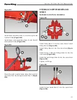
Figure 181
Locate one each of the following components:
• 08 MNPT x 08 MNPT 90° Elbow (Item 1)
• 08 FNPT One Way Flow Control Valve (Item 2)
• 08 x 10 MJIC x 08 MNPT Hydraulic Hose (Item 3)
[Figure 181]
Apply teflon tape to the male threads of each
fitting.
Install the 08 MNPT x 08 MNPT 90° elbow into the
flow control valve.
Install the 08 x 00 MJIC x 08 MNPT hydraulic hose
into the 08 FNPT One Way Flow Control Valve.
NOTE:
Place a collection container under the
hydraulic cylinder ports before removing
the plugs.
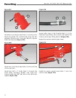
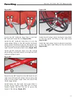
Figure 182
Remove the plastic plug from the base end (upper)
of the hydraulic cylinder.
Install the flow control valve assembly (Item 1)
into the hydraulic cylinder. Tighten all connections.
Remove the protective plastic (Item 2) from the
hydraulic cylinder
[Figure 182]
.
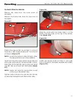
Figure 183
Remove the plastic plug from the rod end (lower)
of the hydraulic cylinder.
Locate and install the 08 MORB vent plug (Item 1)
into the hydraulic cylinder
[Figure 183]
.
1
1
1
2
2
3
1
1
Summary of Contents for 1370
Page 1: ...062019 FK429 ASSEMBLY MANUAL BACKSAVER AUGER Models 1370 1385 1395 13114...
Page 2: ......
Page 92: ...Assembly 1370 1385 1395 13114 Backsaver Auger 90...
Page 93: ......


