Assembly - 1370, 1385, 1395, 13114 Backsaver Auger
80
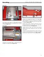
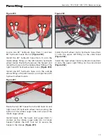
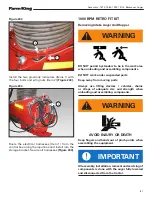
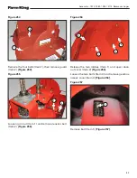
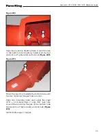
Figure 239
Right hand (RH) and left hand (LH) sides of the
hopper are as viewed from the end of the hopper,
looking towards the intake auger (Item 1)
[Figure
239]
.
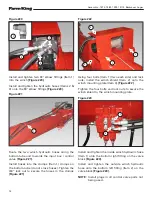
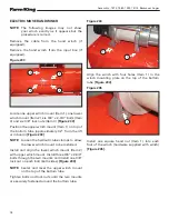
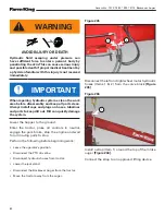
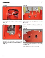
Figure 240
Install the left hand (L) electric motor / wheel
assembly (Item 1) onto the hopper using three
3/8” x 1” bolts and 3/8” lock nuts. Tighten bolts
and nuts
[Figure 240]
.
Repeat for installing the right hand (R) electric
motor / wheel assembly.
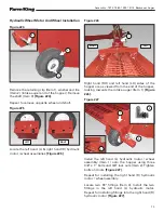
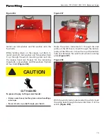
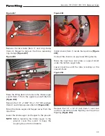
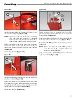
Figure 241
Install wiring harness connector (Item1) to right
hand (R) electric motor wheel harness connector
(Item 2) as shown
[Figure 241]
.
Repeat procedure for the left hand (L) electric
motor.
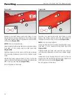
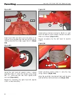
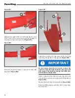
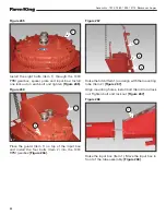
Figure 242
Install proximity sensor (Item 1) onto the ring
clamp (Item 2)
[Figure 242]
.
Align the proximity rails (Items 3 & 4) with the tabs
and install four bolts and lock nuts
[Figure 242]
.
1
1
1
2
1
1
2
3
4
RIGHT
LEFT
Summary of Contents for 1370
Page 1: ...062019 FK429 ASSEMBLY MANUAL BACKSAVER AUGER Models 1370 1385 1395 13114...
Page 2: ......
Page 92: ...Assembly 1370 1385 1395 13114 Backsaver Auger 90...
Page 93: ......


