Assembly - 1370, 1385, 1395, 13114 Backsaver Auger
34
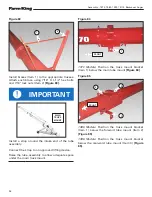
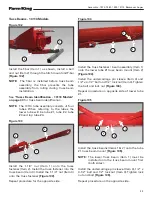
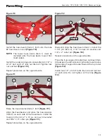
Figure 106
Raise the truss beam assembly (Item 1) and the
truss beam (Item 2)
[Figure 106]
.
Place the truss spacers (Item 3) on each side of the
truss beam, install the truss pin (Item 4), 2” x 10
ga. narrow rim washer and 5/16” x 3” cotter pin
[Figure 106]
.
Repeat procedure on the opposite side.
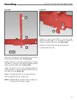
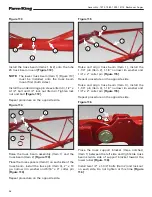
Figure 107
Raise and align truss beam (Item 1), install the
1-1/4” pin (Item 2), 1-1/4” narrow rim washer and
1/4” x 2” cotter pin
[Figure 107]
.
Repeat procedure on the opposite side.
Truss Support Bracket Assembly
See
"Trusss Beam Identification - 13114 Models" on
page 40
for truss support bracket identification.
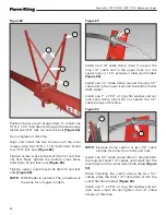
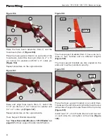
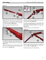
Figure 108
The truss support brackets (Item 1) have one, two,
three or four notches and are different lengths
[Figure 108]
.
The truss support brackets are also angled on the
ends and must be installed correctly.
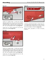
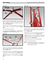
Figure 109
Place the truss support bracket (one notch) (Item
1) between the left side and right side truss beams
(wide side of support bracket toward the top tube)
[Figure 109]
.
Install two 1/2” x 1-3/4” bolts (Item 2) and lock nut
on each side. Do not tighten at this time
[Figure
109]
.
1
1
1
1
2
2
2
3
4
3
ANGLE
ANGLE
NOTCH
WIDE SIDE
WIDE
SIDE
Summary of Contents for 1370
Page 1: ...062019 FK429 ASSEMBLY MANUAL BACKSAVER AUGER Models 1370 1385 1395 13114...
Page 2: ......
Page 92: ...Assembly 1370 1385 1395 13114 Backsaver Auger 90...
Page 93: ......


