2.
JR —
Refer to Appendix C, for instructions for using the TA
torque assist removal tool.
ALTERNATE METHOD —
Loosen the setscrew on the
bushing nut which is located at the output end of the
hollow shaft. Use a spanner, pipe or chain wrench to
loosen the bushing nut (Section I, Table 6). Initially, the
nut will freely rotate counter clockwise approximately
180° as the nut moves from the locked position to the
removal position. At this point anticipate resistance which
indicates unseating of the bushing. Continue to turn the
nut until it is free from the hollow shaft. Prepare drive for
lifting (Figure 7, Page 6) by disconnecting the tie rod at
the drive end. Slide the drive from the bushing. The
bushing can be left in place or removed, as required. If
bushing will not slide off of the shaft, insert a small prybar
into the split of the bushing and pry the split open slightly
to loosen the bushing and remove from the shaft. For
replacement of seals only proceed to Step 5, otherwise
Step 9.
3.
JF —
Remove the output shaft cover, Ref. #14 (Figure 14,
Page 14), from the input end of the hollow shaft. Remove
the bolts which fasten the mounting flange to the driven
equipment.
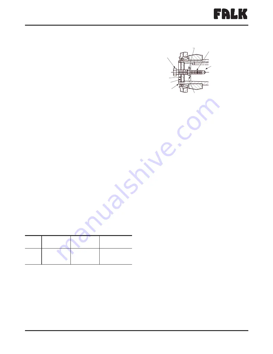
Remove the fastener, retaining ring, and thrust plate from the
hollow shaft. Refer to Table 10 and select a backing bolt
and flat washer and install them into the drive shaft as
illustrated in Figure 11. The bolt head provides a working
surface for the removal bolt. Reinsert the thrust plate and
retaining ring into the hollow shaft and select a removal bolt
from Table 10. Thread the removal bolt into the thrust plate
until it contacts the backing bolt head. Torque the removal
bolt to the value shown in Table 10. (If the thrust plate
rotates in the shaft, align the slot in the plate with the hollow
shaft keyway and insert a screw driver or piece of key stock
to prevent rotation of the plate). After torquing the bolt, as
instructed, strike the bolt, sharply with a hammer and
retorque the bolt if separation of the drive from the shaft did
not occur. Repeat this procedure, retorquing the bolt after
each blow, until separation occurs.
CAUTION:
Failure to follow this procedure may result in the
destruction the threads in the thrust plate. (If the retaining
ring becomes damaged, refer to Appendix H, for
replacement information).
Proceed as follows:
JF to Step 5 for replacement of Quadrive seals only OR Step
9 for drive disassembly procedure.
4.
JSC (4407 only) —
Prepare drive for lifting as shown in
Figure 7, Page 6. Remove drive from driven equipment
trough end by removing the trough end mounting screws
from seal housing. Remove coupling bolts from drive
shaft and slide drive with drive shaft away from the driven
equipment.
To remove drive shaft from the drive, remove the output
shaft cover, Ref. #14 (Figure 14, Page 14), from the input
end of the hollow shaft and then refer to Step 3 above. The
procedure to separate the JSC drive from the shaft is the
same as for separation of a JF drive from driven equipment
shaft.
After separation of the drive and shaft has been achieved,
determine the type of seal equipped in the seal housing. If it
is a waste packing seal, remove the waste packing material
and then remove the loosened drive shaft from the seal
housing side of the drive. If equipped with a lip seal, first
remove the lip seal following the removal instructions from
Step 5 below. After seal is removed from seal housing,
remove the loosened drive shaft from the seal housing side
of the drive.
CAUTION:
The seal housing acts as the bearing cage,
therefore, NO NOT remove from the drive unless complete
drive disassembly is anticipated. Removal of the seal housing
will require readjustment of the L.S. bearings (Section III,
Page 21).
The Falk Corporation, P.O. Box 492, Zip 53201-0492
378-102
3001 W. Canal St., Zip 53208-4200, Milwaukee, WI USA Telephone: 414-342-3131
August 2004
Fax: 414-937-4359 e-mail: [email protected] web: www.falkcorp.com
Supersedes 6-92
®
a good name in industry
Owners Manual
•
Quadrive Shaft Mounted Drives
(Page 10 of 56)
Sizes 4407/M4407-4608/M4608
TABLE 10 — Removal & Backing Bolt Size and
Length – Inches
Drive
Size
Removal Bolt
Size & Minimum
Length
Maximum
Tightening Torque –
lb-in (Nm)
Backing Bolt
Size & Maximum
Length
4407
1.125-7UNC x 3.00
8900 (1 006)
1.000-8UNC x 2.50
4415
1.500-6UNC x 3.75
22100 (2 497)
1.250-7UNC x 2.75
4507
1.500-6UNC x 3.75
22100 (2 497)
1.250-7UNC x 2.75
4608
1.500-6UNC x 3.75
22100 (2 497)
1.250-7UNC x 2.75
RETAINING
RING
THRUST
PLATE
REMOVAL
BOLT
BACKING BOLT
TAPPED HOLE
IN DRIVE SHAFT
DRIVE SHAFT
FLAT WASHER
HOLLOW
SHAFT
Figure 11


